This is hobbyist style build based on the Motorola MEK6800D2 from about 1979.
When i collected the MicroVAX I from the seller, Jan, she showed me this unusual machine. Her late husband, Andrew had built the machine back in about 1979. It obviously became an enduring treasure. The family generously donated this machine to me for which i am very grateful. It gives me a real kick to restore a machine that has been important to someone.
The case is a little agricultural, but it has nobly protected its innards for 45 years. The cards and backplane are in very good condition.
The machine carries the moniker of “Deep Thought” as a nod, no doubt, to “The Hitchhiker’s Guide to the Galaxy”. The name is hardly unusual but it is the only one i have so that is what i will call it.
I expect that this machine was built, modified, and expanded over several years. Andrew would have started with the Motorola Evaluation Kit II (MEK6800D2). This kit was for evaluation of the 6800 processor ie it is a little like an MCS85 System Design Kit for the Intel 8085 processor. These types of kits could also be used in teaching labs or by hobbyists, although machines like the Heathkit ET-3400 provided a more polished alternative.
The kit included a single board computer based on the 6800 processor. It included a 1kB ROM with the JBUG system monitor, 384 bytes of RAM, a serial port and a cassette port.
The MEK6800D2 is a little unusual in that Motorola provided many off the shelf enhancement options. Andrew added a video/keyboard, I/O, and 32k Memory cards. An ROM monitor, CRTBUG, for video/keyboard card has also been added.
Along the way it seems that some older functions have been removed. It looks like there were once some connections to a parallel port, for example.
A folder with a few notes has survived but no cassettes have surfaced (as yet).
The MEK6800D2 kit is well documented in manuals available online, but the additional cards are more unusual and so far i have not found a lot of information on them – just enough to get started.
I aim to get this machine running from the installed ROM monitors. Ideally i would like to be able to load some sample programs via the serial interface and save and load from cassette. I have a 6800 cross-assembler that runs under CP/M but i’d obviously prefer a cross-compiler in C or Pascal.
I would like to retain the personality of the build, but some changes are inevitable – particularly to make the unit safe and robust.
The lid was already begging to be removed and curiosity demanded it.
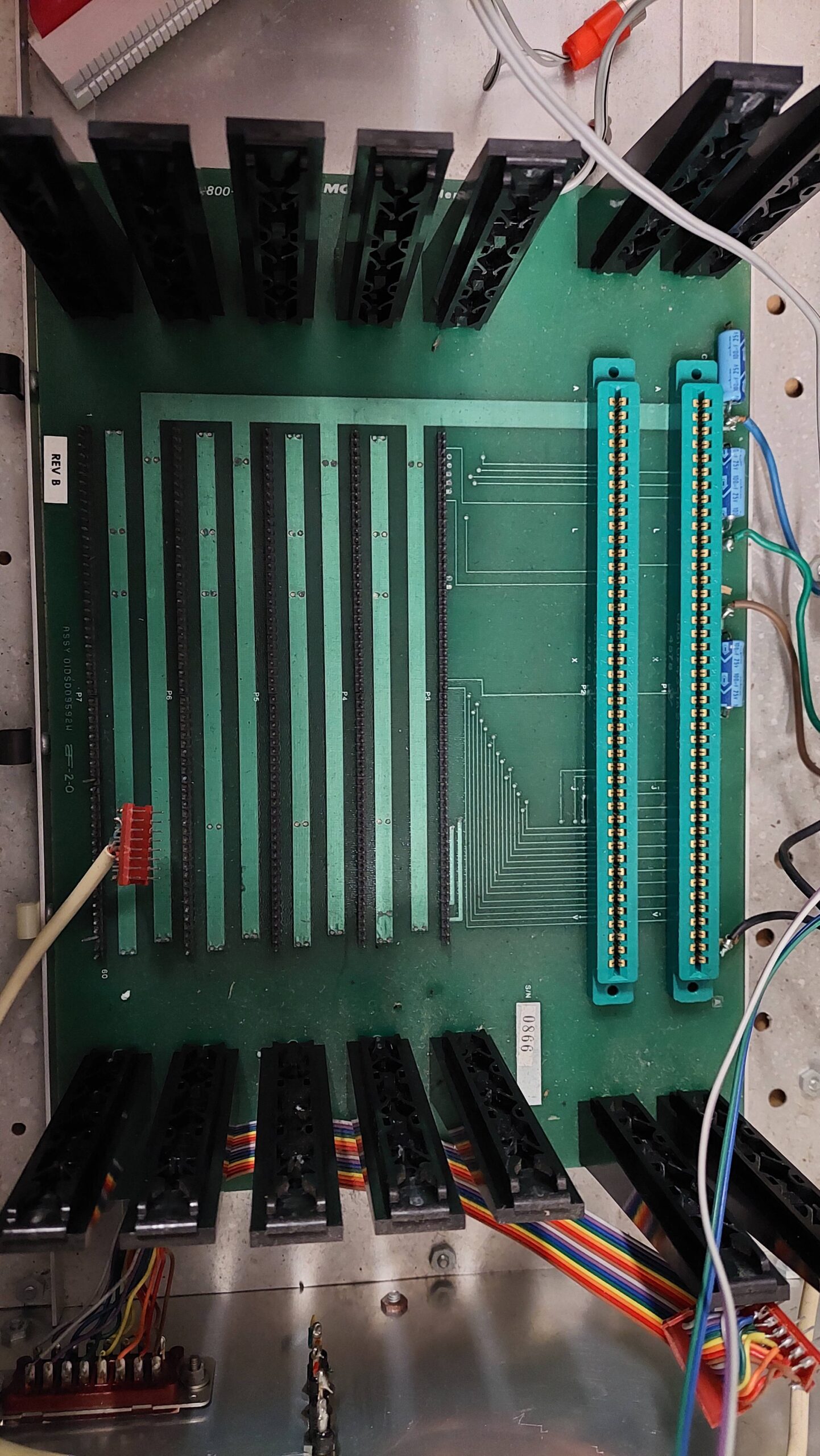
The unit contains a MEK6800AB backplane with:
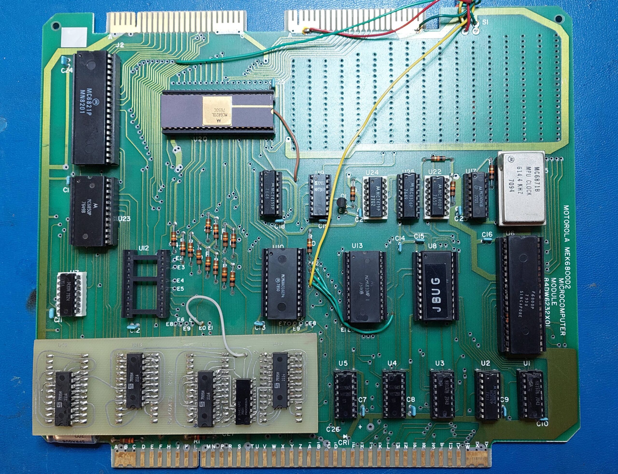
MEK6800D2 Processor Card
MEK68 I/O Card
MEK68MM32 32kB Memory Card
MEK68R2 Video card
There are several connections to the cards including coaxes for the cassette interface and the video output, and a DIP connector for the RS232 line.
The front panel card (must get a photo) connects to the processor card by a bright red ribbon cable. This was disconnected and that be be deliberate.
The bus interface on the processor uses an edge connector whereas the other cards use a SIL connector. The former is consistent with Motorla EXORciser Bus and the latter is referred to as the Motorola Kit Expansion Products (MOKEP) interface.
The processor card includes the 6800 processor, which seems to be suffering some corrosion – a common occurence with ICs using silver plate rather than tin.
It also has two different Parallel Interface adapters: an MC6821 and an older MC6820 (in a ceramic package). There are two ROMs. One is clearly the JBUG ROM. The other is presumably the CRTBUG ROM. The third ROM socket is unoccupied. There is a 128B RAM which is used by the JBUG ROM program. The 4x 128B RAM sockets in the lower left have been filled with an Australian produced RAM daughter-board that provides a massive 2kB!
There are clearly some mods, one of which i expect is to select between the two onboard monitor programs using a front panel switch. A front panel reset switch is wired directly to the S1 footprint.
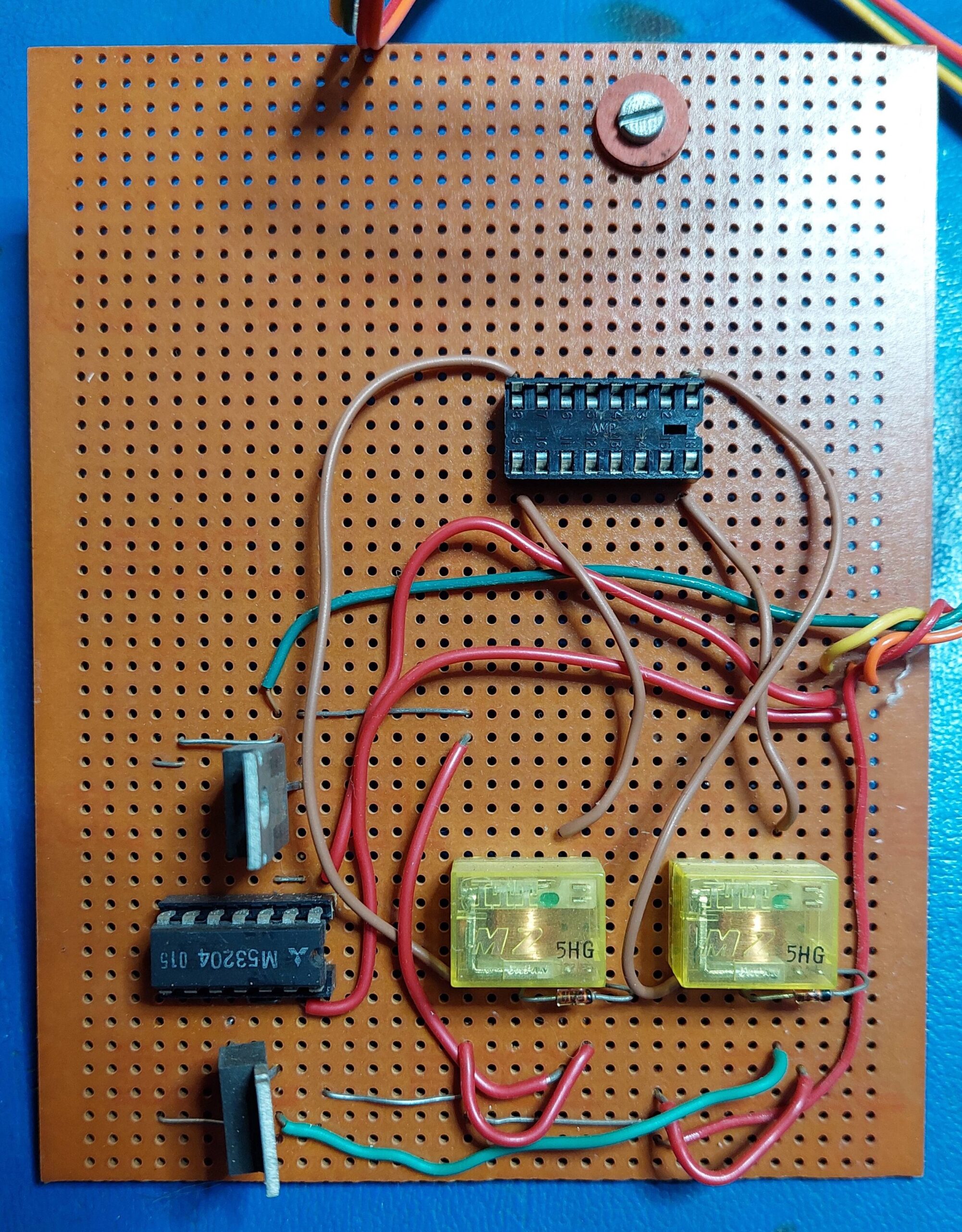
The two upper edge connectors are for the PIAs. One of these is used to connect the keypad/display board. The other is user defined – it appears to be used for a small I/O board (get photo) – two relays and drivers, i think.
The keypad/display card connects to the processor card using a ribbon cable. It also has some circuitry for the cassette interface.
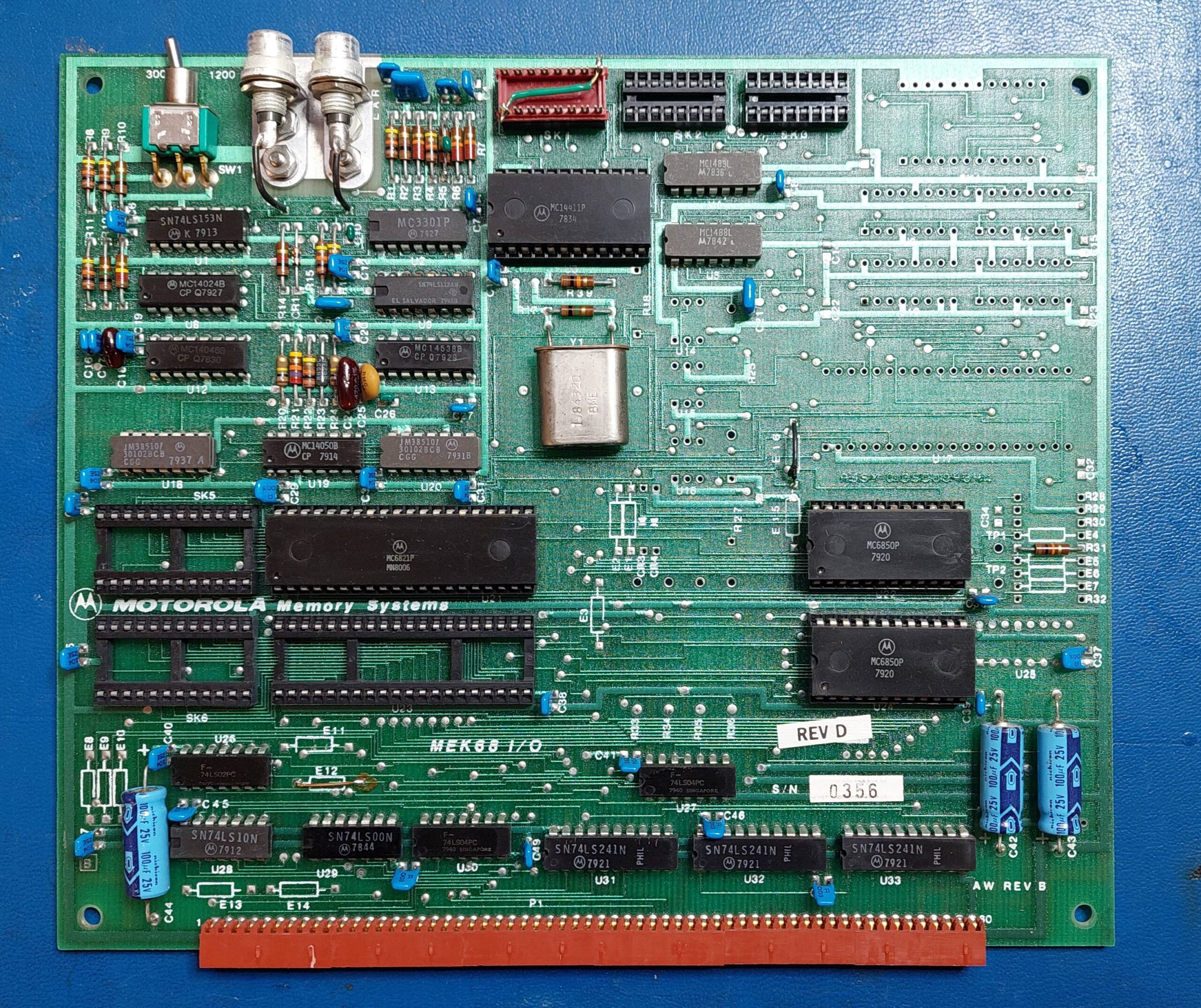
The I/O Card is not fully populated. There are two Asynchronous Serial Interface Adapters (ACIA); one for the cassette interface and one for an RS232 port. There is one Parallel Interface Adpater (PIA) and provision for one more. I/O connections are made via loathesome 16 and 24 pin DIL cable connectors. There is a switch to select 300 or 1200 baud on the cassette interface and two RCA connectors for same. There is a manual available for this card.
The video card uses the popular MC6845 video controller. It has 2kB of RAM so should support 80 columns by 24 lines. I have not located a manual for this card. Hopefully it will just work with the CRTBUG monitor and the keyboard otherwise i’ll have some reverse engineering to do.
The RAM card is populated with 32kB of dynamic memory. Again, i haven’t been able to find a manual for this but i assume that it is located at 0000 and overlaps with the processor card RAM and option ROM. Perhaps some of the mods on the processor card take care of this.
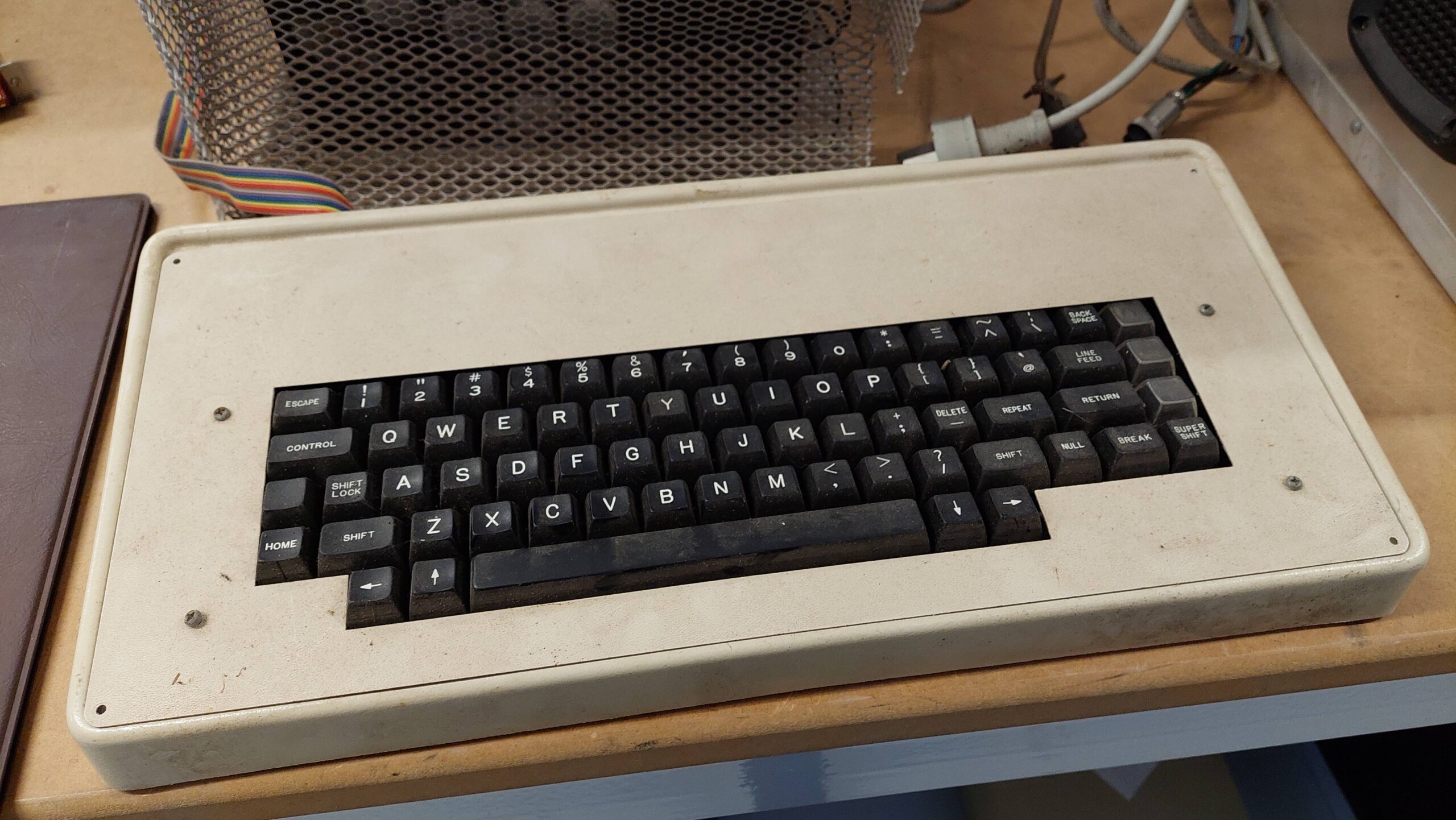
The ASCII keyboard uses a mask programmed Intel 8048 microcontroller with what is likely to be a custom version of the General Instrument AY-5-2600 Keyboard Encoder.
The MEK600D2 has a standard configuration as supplied by Motorola. In this configuration it runs the JBUG monitor from a mask programmed ROM.
The memory map is as follows:
The memory space is not fully decoded though. The main decoder divides the 64k space into 8x 8k blocks. The JBUG ROM, for example is mirrored 7 times – which is probably how it is able to boot in the first place as reset causes execution to start at the top of memory.
The I/O appears even more curious with the address ranges of devices overlapping ie it would be possible to enable multiple devices at the same time using undocumented addresses. eg the One PIA is active when A2=1, the second PIA is active with A5=1, and the ACIA is active with A3=1.
The processor board has been modified with a 2k RAM board, so the RAM occupies the space from 0000H to 07FFH. Or at least that would be the case if other modifications had not been made.
It is also curious that there is a separate 128B RAM block set aside at A000H for the JBUG stack. This also, occupies a full 8k of memory space.
It seems that the MEK6800D2 expansion with external MOKEP boards was not entirely thought through by the time the D2 was released.
The first example is the 32kB expansion card which requires a contiguous 32k memory block which does not exist in the baseline design. The area from 2000H to 5FFFH was unused (the decode lines (2/3 and 4/5) go to the EXORciser interface.
The remaining area from 0000H to 7FFFH is reclaimed by disabling the expansion PROM at U12, and the re-allocating the RAM at 0000H to the area used for the dedicated JBUG RAM at A000H.
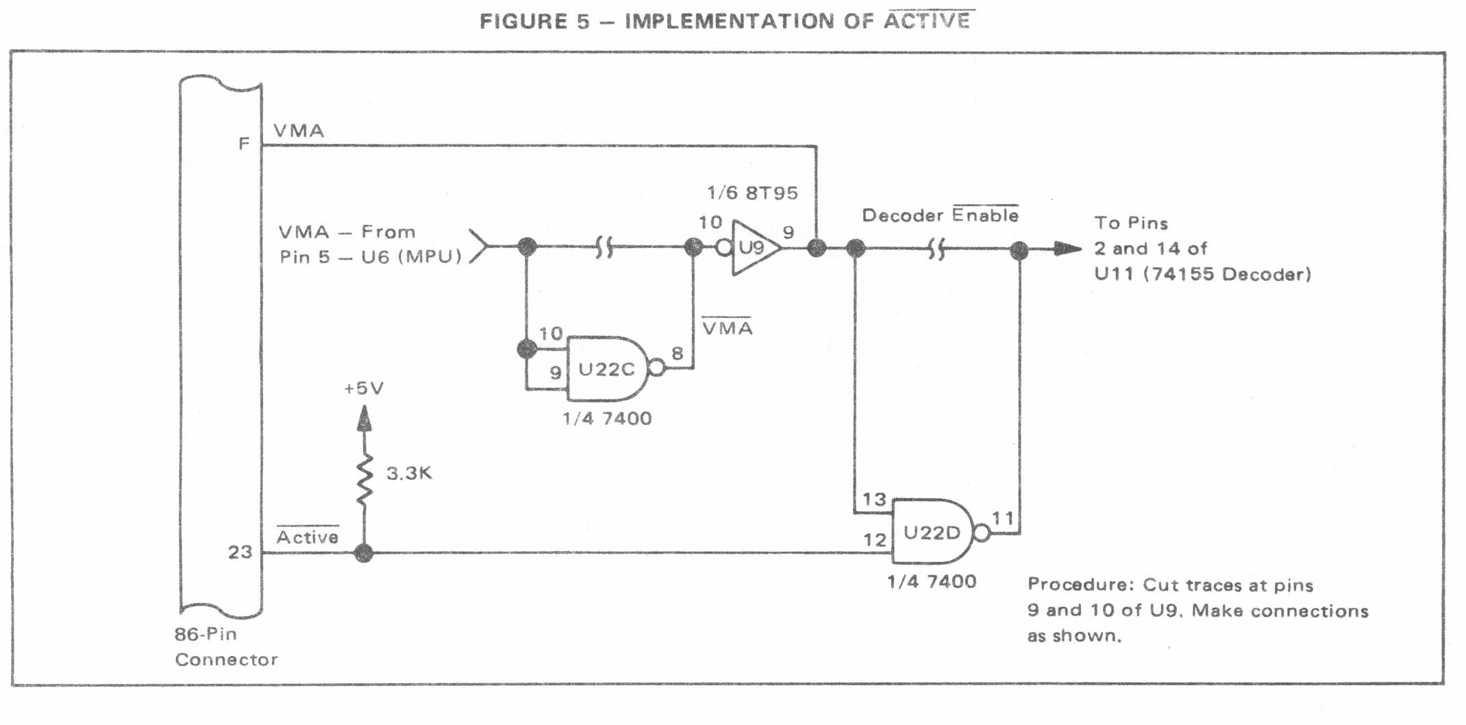
Helpfully, there is an application note that discusses possible modifications to accommodate various MOKEP cards. It highlights the VMA signal that can be externally activated to suppress onboard devices for particular addresses. It also introduces an Active signal which performs a similar function but is open collector so that it can be used by multiple devices. The Active signal was introduced by modification of the processor board:
The Active signal is certainly used by the Video card and may be used by the RAM card. The Video card is active 8040H to 9FFFH so the Processor card decoder I/O output is active only for 8000H to 803FH.
The I/O Card can be configured for 4 different sets of addresses:
The card in this system is configured for option 2.
The I/O Card has not been loaded with the IEEE interface, but the decoding for it does seem to be present. On the face of it there is a potential contention with the Video card at 8058H.
Check what happens with I/O1 – the I/O card expects it but the processor card doesn’t provide it. There are some hints that the Video Card might provide it. What a curious thing.
The card has both the JBUG and CRT ROMs installed. The socket U10 has been modified so that both ROMs are enabled by PROM0_L at E000H. A switch is used to enable one ROM at a time.
There seems to be no device at C000H. It may be possible to move the ROM (U12) that was at 6000H to this location. This ROM has a lot of configuration options so it may be possible to configure the slot for a 2716 EPROM or even a 2732 EPROM. This would be very handy for routines to use the serial ports.
There are mods on the back of the keypad and display but they appear consistent with the schematic in the manual so perhaps they were covered by a note with the kit or were a service update. They are:
The power supply looked like it had suffered a little. The cheese-grater enclosure was neither robust nor dust proof.
It was fairly easy to remove the case. I’m all for keeping things original, but mains power needs to be taken seriously. Inside i found an off the shelf Motorola open frame linear power supply.
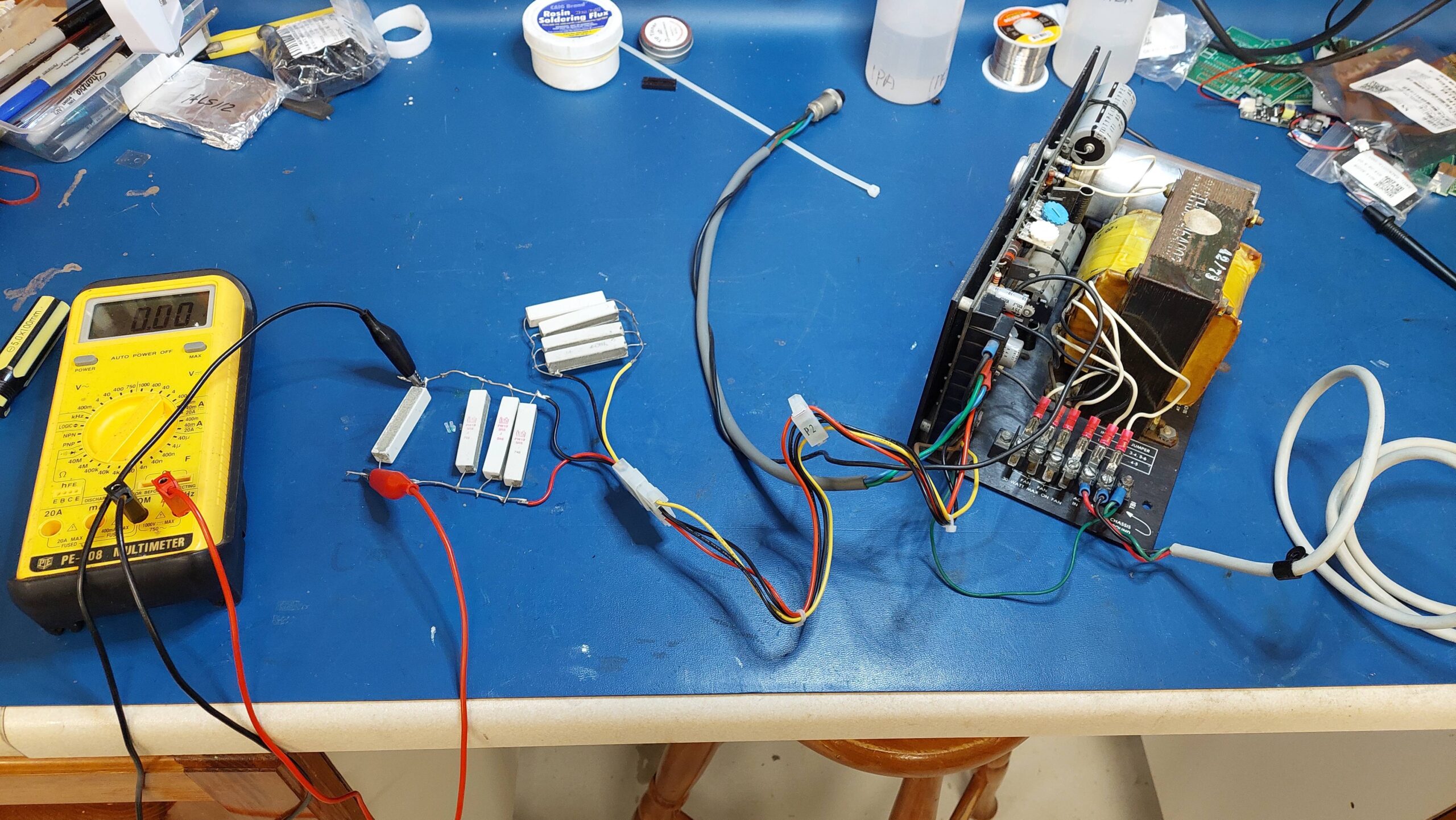
It is the perfect companion for the computer so i set about cleaning it up. There were no obvious issues so i powered it up using an autotransformer.
I brought it up slowly without load and it survived the experience. The voltages were pretty good. I added a nominal load and it seemed to hold up fine.
The power supply has two designated connection points for mains fans. One was used for a fan attached to the cheese-grater case, and the other connects to a fan in the computer case. This is not great because it involves a live plug (ie live pins), and the computer case is not clearly earthed.
The power supply does claim short circuit protection, but the chassis wiring does not include a fuse. The mains cable has become quite stiff with the passing years; i will replace it.
The DC cabling is re-used 10A mains cable. It does not make use of the sense inputs on the power supply.
I think it is probably worth starting afresh on the power supply chassis.
I had already cleaned the power supply and tested with a small load.
The enclosure really needs some work and the cards would be hard to access inside the case, so decided to pull all the connectors and cabling out. I gave it all a clean and set it up on the bench.
In preparation for power on, i applied de-oxit to all of the socketed ICs and reseated them.
I started with the backplane and power supply. I checked all the power wiring several times, fearing that somehow i would get the voltages muddled. Then i powered up and nothing bad happened with the backplane alone.
Then i added the processor card and checked voltages. Still ok, so i added the keypad/display card. The 5V at this card was starting to get a little low. I think the regulation would be improved markedly if the power supply sense lines were used.
On power up nothing was displayed. I tried the reset. The switch feels terrible but is just working. Still no display. Then i toggled the CRTBUG/JBUG switch and reset again. This go the dash (-) display that was expected. Splendid news indeed.
The requirement for a manual reset at power on seems a little primitive.
I did a crash course on JBUG and was able to enter some commands and edit some memory locations. There was no memory at 0000H, but there was 2kB of memory at A000H. That’s consistent with the mods.
Next i added the 32kB memory card which also seemed to work fine.
Next i added the Video card and connected a monochrome video monitor. This required toggling the CRTBUG/JBUG switch and hitting the reset again. After some adjustment of the horizontal sync on the monitor i got a CRTBUG 1.0 sign on message. This was a lot of progress in a short time.
I was able to start up either monitor using the switch provided for that purpose. I assume it is messing with the chip enables on the two ROMS.
Then i added the ASCII Keyboard and progress ground to a halt. The only key that seemed to work was the space bar. I added the I/O card in the just to confirm it made no difference. It did make no difference.
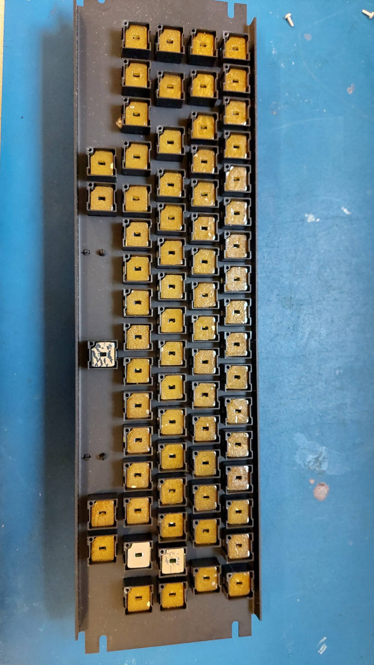
When i looked closer at the keyboard i noticed that there were no key switches soldered in. I removed the screws and quickly found that the board is a capacitive type similar to that used on the Kaypro II and the Compaq Portable.
These keyboard use foam pads with a conductive layer on plastic. Typically, both the foam and the conductive layer deteriorate and need to be replaced. In this case only a few pads had retained their conductive layer – one of them is the space key.
Replacement is laborious and made worse by their complex shape. This is a job that can wait until after i have confirmed that the computer itself is working well.
Until then, i can use a PS/2 keyboard with an adapter to make it appear as an ASCII keyboard. I’ve done this before with a Microlog Little Video Board. Once the pinout was sorted (with some buzzing followed by guesswork) the keyboard was good and i could enter commands using the CRTBUG monitor.
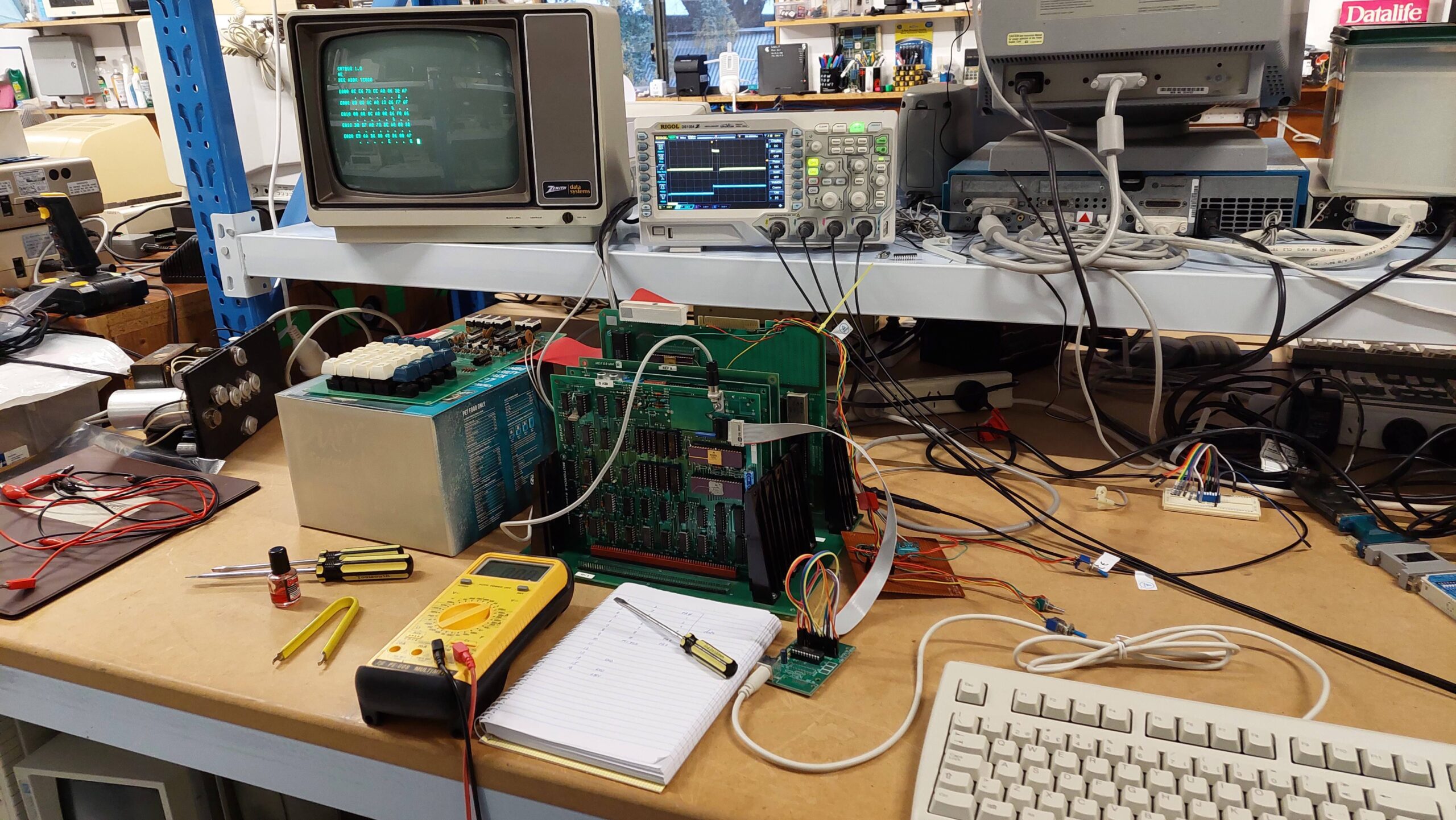
The CRTBUG monitor is a lot easier to use than JBUG so i could do rough write/read tests on the RAM.
I found that the Zenith monitor struggled with the horizontal sync, but the video seems fine on a modern video monitor.
I should see if i can jump to CRTBUG from JBUG.
There are cassette ports on both the processor card and the I/O card. JBUG is made for operation with just the MEK6800D2 so it would use the interface on the processor card. I was not sure what the CRTBUG would do, but when i “punched” to tape it definitely used the one on the processor card.
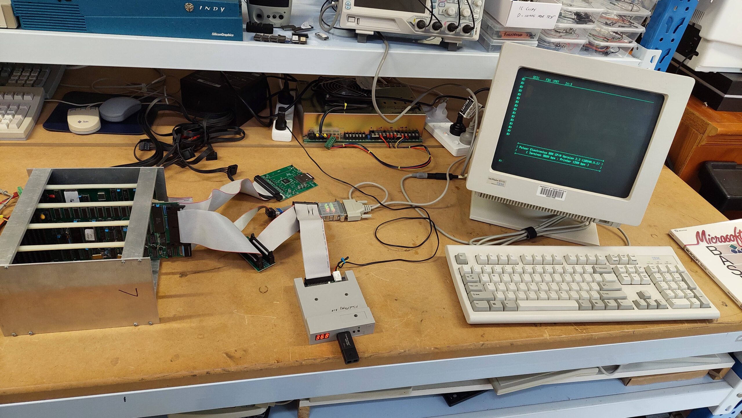
I have several machines based on Pulsar single board computers. A couple of these are running multiple processors and therefore require the capabilities of TurboDOS.
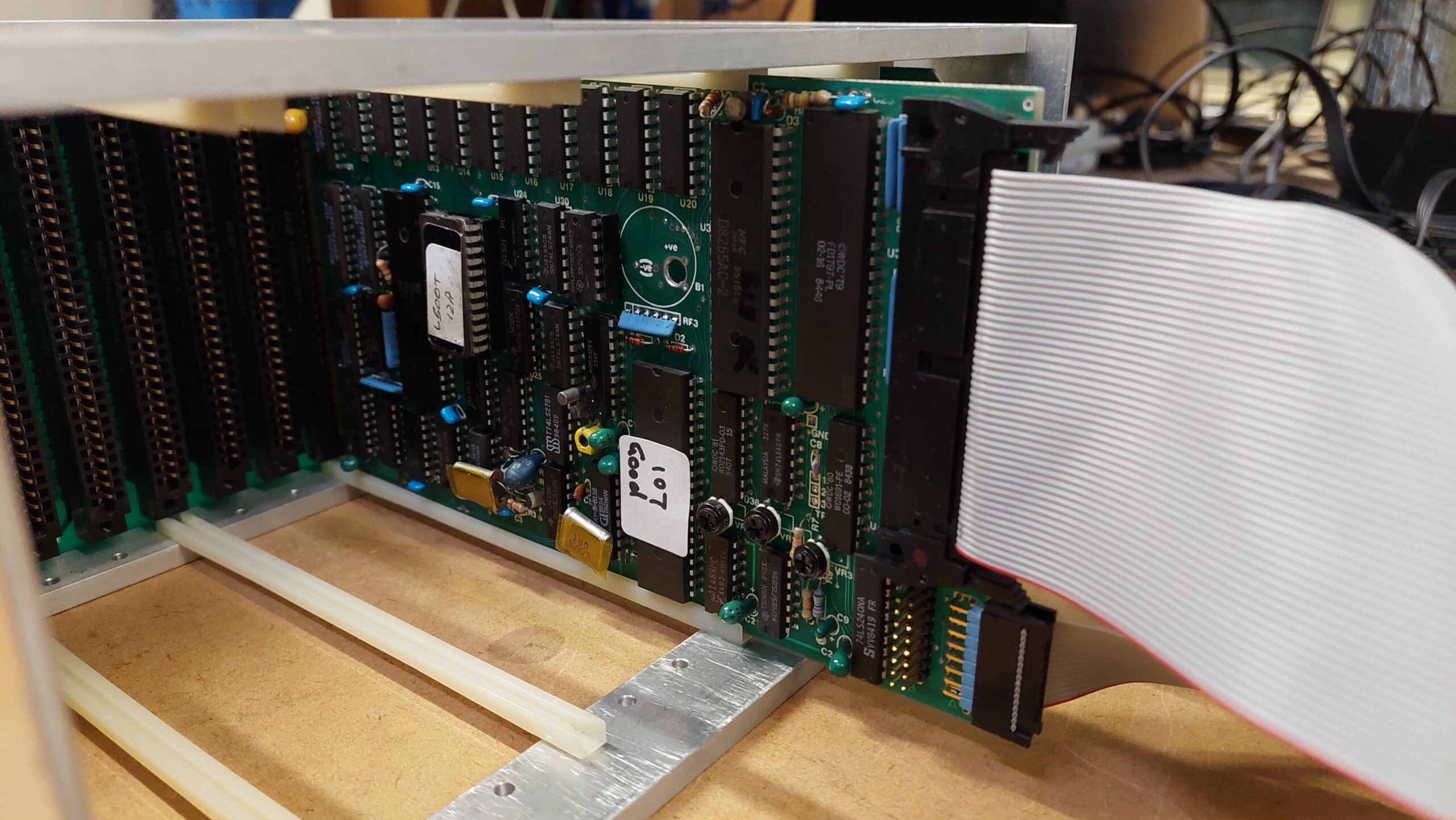
One that i have previously written about, the Little Big Board Computer, uses a single Little Big Board (LBB). This machine can happily run either TurboDOS or CP/M. It uses two 8″ floppy disk drives which gives it a generous 2.4MB of online storage which is pretty handy for CP/M – certainly better than the 280kB of storage that i had on my old Apple II clone back in the eighties. Nevertheless, after using the hard disk based TurboDOS systems it seems a little inadequate.
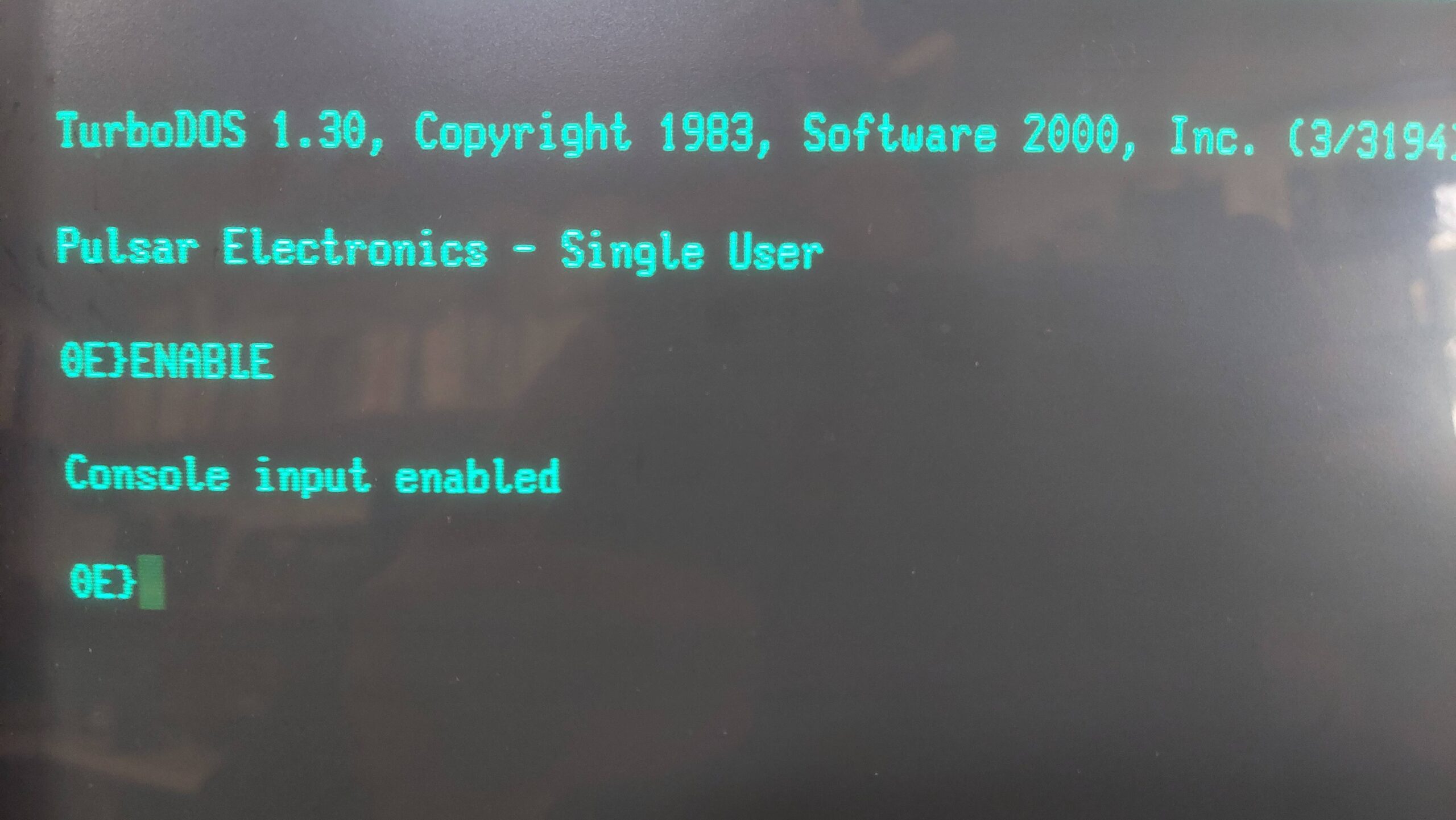
Another computer based on the LBB is the Pulsar 7500. This machine uses five LBBs with one as a master and the other four supporting one user each. Using an installation process similar to that used witht the 7500, i had previously set up an LBB with a SASI card, and had installed TurboDOS on a solid state hard disk as a single-user system. I used it to try out a Little Video Board. This is a perfect system for trying out a hard disk on Pulsar CP/M.
There were certainly hints that the Pulsar CP/M had hard disk support but how it all worked was clouded in mystery due to the absence of any Pulsar CP/M documentation. I’m sure it existed but i have never found any.
I figured that if the support was there, then it could be lurking on some 8″ Pulsar CP/M disks that had originated from the same source as the Pulsar hardware.
All of my 8″ disks have been imaged and, for most, the files have been extracted. This meant that i could run some searches using a modern PC and from there i could have a survey the various files of interest.
Out of the 115 viable Pulsar CP/M disks i found 6 that had a program called hform, which isounds a lot like a hard disk formatter.
One of these disks, 103, was labelled “Pulsar CP/M 2.2 (Update 6) CP/M 2.2 Configuration Disk”. It contains a lot of assembler files, library files (includes), and some scripts. There was also a file called note-32 and that contained a lot of useful instructions on how to build a hard disk CP/M system for the LBB.
Contents of notes-32
                NOTES ON ASSEMBLY OF PULSAR BIOS

         A new utility called 'ASSIGN.COM' has been provided.
         This allows any drive to be swapped with Drive A:.
         This permits programs such as copy to work
         correctly even when booting up from the hard disk
         which normally signs on as Drive A: when hardboot
         is selected. (Note that the hard boot loader and
         hard boot prom must be used when the hardboot
         option is selected.

         Also another utility called 'STOPLIST.COM'. This is
         used when you wish to abort the buffered print mode
         (otherwise you may have to wait for up to 63k of
	 buffered print to finish) when using the RAM card
	 buffer.

	 A utility called 'CON.COM' has also been added.
	 This displays the current configuration of your
	 BIOS.


     1.   Set switches in CPMSYS.LIB for the following :

          - Hard disc present  (HARD : true/false)
          - Hard disc split into up to 4 drives  (NUMHARD : 0..4)
          - Reserve hard disk boot tracks  (HBOOTRAK : true/false)
          - Boot from hard disc            (HARDBOOT : true/false)
          - Large hard disk directories    (LARGEDIR : true/false)
          - Virtual RAM disc present (VDISC : true/false)
          - Printer buffer present up to 63K  (PRINTBUF : 0..63)
          - Number of RAM cards (RAMCARDS : 1/0)
          - Floppy interface side select line used
                                   (SIDESEL  : true/false)
	  - Large directory on floppies  (EXPDIRF : true/false)
				only works if SIDESEL is true

	  [ If sidesel is true then LBB can control up to 4
         double-sided drives but cannot read old dual-directory
         disc format since hardware won't read address marks
         with side field = 0 while side select line active ]

         CAUTION: If using hard disk in system, and you change
         any parameters (large directory, boot tracks or
         split operation) then you should FIRST back up your
         hard disk, re-format it, change the system and copy
         back your files to the hard disk !

	 ****************************************************
	 *						    *
	 *  Format4 must be used with a side select system. *
	 *						    *
	 ****************************************************

     2.   If generating a hard disc system set switches in
          CPMSYS.LIB for the following :

          - Xebec or DTC controller (XEBEC : true/false)
          - Make/model of hard disc drive (set only one true)


     3.   Set switch in CPMSYS.LIB for the following :

          - Slow or fast floppy drive step rate
          (SLOWSTEP : true/false i.e 10 or 3 msec track to track)


     4.	  - The bios version part of the sign-on shows you which
	  flags have been set.

 	  - normal bios		(LB31A...D)
	  Slowstep=false, Hard=false, Ramcards=false, Sideselect=false

   	  - custom bios		(LB31ASHML)
	  Slowstep=true, Hard=true, Ramcards=true, Sideselect=true

     5.   Assemble your new bios :

	  e.g.  M80 =$1
          	L80 $1/N,$1/M/X/E

        Note that some later versions of L80 (e.g. 3.44)
        have been found to be unsuitable as they load
        hex from from address 100h instead of the stated
        origin (e.g. bios)

        Take note of which submit file & parameters to use.
        (E.g. use ctrl-P to print if possible)

        Assemble the loader indicated during bios assembly.

        Generate the CPMXX system image indicated using MOVCPM.

     6.   Link your bios with it's loader and CP/M .

          - For 62K floppy boot systems SUBMIT DGEN62 LBLDR9 LB31A
          - For 61K floppy boot systems SUBMIT DGEN61 LBLDR10 LB31A
          - For 60K floppy boot systems SUBMIT DGEN60 LBLDR11 LB31A

          - For 61K hard boot systems SUBMIT HGEN61 LBHLDR10 LB31A
          - For 60K hard boot systems SUBMIT HGEN60 LBHLDR11 LB31A

          DGEN62.SUB
          ;use: submit dgen62 <loadername> <biosname>
          ;inputs: loadername.hex, biosname.hex, cpm62
          ;xsub.com, zsid.com  must be on default disc
          ;creates system file biosname for sysgen
          XSUB
          ZSID
          ICPM62
          R180
          I$1.HEX
          R880
          I$2.HEX
          R
          G0
          SAVE 50 $2
          ;PLEASE REBOOT ... SYSGEN DOES NOT RUN UNDER XSUB

          HGEN61.SUB
          ;use: submit hgen61 <loadername> <biosname>
          ;inputs: loadername.hex, biosname.hex, cpm61
          ;xsub.com, zsid.com  must be on default disc
          ;creates system file biosname.hrd for sysghard
          XSUB
          ZSID
          ICPM61
          R180
          I$1.HEX
          R880
          I$2.HEX
          R
          G0
          SAVE 54 $2.HRD
          SYSGHARD
To add a hard disk I had to reconfigure and rebuild the CP/M BIOS. I’d never done that before so i figured it would be an adventure.
The file CPMSYS.LIB (an ASCII file) contains parameters for the BIOS including the hard drive, controller type, and SASI interface type. In the early eighties hard drives typically had a ST506 interface (often referred to incorrectly as an MFM interface). To convert these drives to SASI (the original name for the SCSI interface) a controller, eg an Adaptec ACB-4000 was required.
Although i have several of the Adaptec controllers, practically it is far easier to emulate a SASI/SCSI drive eg with a SCSI2SD than it is to find a viable ST506 compatible hard disk. I have already used SCSI2SD on other systems to emulate an Adaptec controller and companion disks. TurboDOS, for example, will boot from a SCSI2SD on an LBB so i’m hopeful that the same setup will work for CP/M.
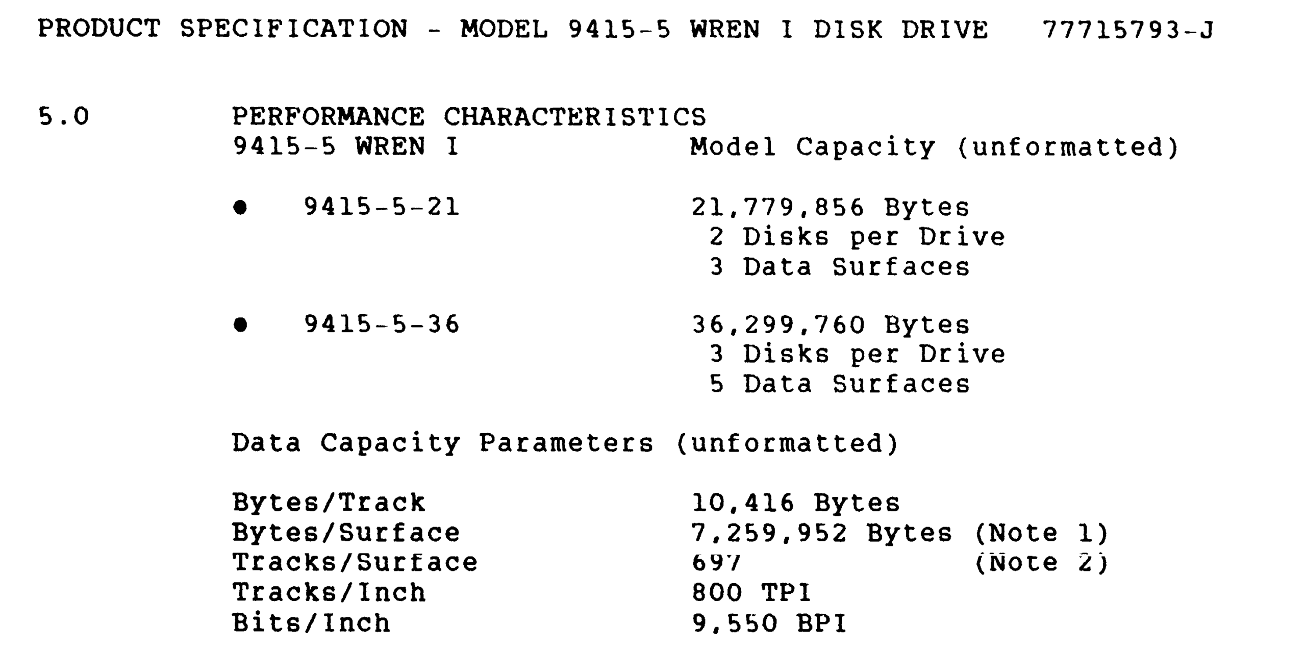
I generally try to use the largest hard disk that the BIOS and Formatter will support. The latest formatter on Disk 103 is HFORM19. It supports many hard disks from the period, the larger ones of which are:
CDC 9415-5 Wren (5 surfaces) 31.3MB
Disctron D526 20MB
Rodime 204 Series 23.1MB
The CDC 9415-5 Wren is a little confusing because there are two sizes. The 31MB version has 3 “disks” and 5 surfaces and the smaller unit has 2 disks and 3 surfaces, whereas the CPMSYS.LIB file refers to 2 or 3 platters which i think must be the same as a “disk”.
If my understanding is correct then CPMSYS.LIB supports the larger CDC drive. It also supports the smaller Disctron and Rodime alternatives.
CPMSYS.LIB also supports the Adaptec ACB-4000 and the Pulsar P6204 SASI card (as would be expected). The configuration file has been copied to CPMSYS2.LIB which is configured for a Miniscribe 3012, but i do not have the original hard disk so i’ll be starting with a new emulated disk.
There was also provision in CPMSYS.LIB for configuring floppy drives, a Pulsar RAM card, printer buffer, and virtual disk.
The maximum supported logical disk size is 1024 x 8kB blocks ie 8MB but, there is provision for breaking a physical drive into multiple logical drives up to a maximum of 4.
The CDC disk has 697 cylinders, 5 heads, and 32x256B sectors per track which i make to be 27.2MiB or about 28.5MB (so the original number was probably “unformatted”). This can become 4x 6.5MiB logical drives.
CPMSYS2.LIB was edited accordingly. This file is included by the BIOS code, LB34A.MAC. The larger hard disk comes with the penalty of a larger BIOS – presumably related to directory data or buffering. 2k of additional BIOS is set aside if no hard disk is used. With the large CDC drive, 4k is set aside. ie the CPM must be 60k.
Following the instructions in NOTES-32, the BIOS has to be reassembled and linked using the Microsoft Z80 assembler and linker:
M80 =LB34A.MAC
L80 LB34A/N,LB34A/M/X/E
The system also needs a boot ROM (the one that is on the board was ok), and a boot loader for the system track. NOTES-32 says to use the LBHLDR11.MAC as the boot loader for 60k CP/M. The file contents confirm that it is intended for 60k CP/M. Exact instructions for assembly and link are not given but i used the one above as a pattern.
M80 =LBHLDR11.MAC
L80 LBHLDR11/N,LBHLDR11/M/X/E
Then a 60kB CP/M needs to be created.
MOVCPM 60 *
SAVE 60 CPM60
The last thing that is required is a means to write the system track. There is a source file for this: SYSGHARD.MAC. Again following the pattern:
M80 =SYSGHARD.MAC
L80 SYSGHARD/N,SYSGHARD/M/X/E
Then it can all be put together using the 60k hard disk script, HGEN60.SUB which contains:
;use: submit hgen60 <loadername> <biosname>
;inputs: loadername.hex, biosname.hex, cpm60
;xsub.com, zsid.com  must be on default disc
;creates system file SYSGHARD.COM
XSUB
ZSID
ICPM60
R180
I$1.HEX
R880
I$2.HEX
R
ISYSGHARD.HEX
R
G0
SAVE 58 SYSGHARD.COM
This is not quite the same as the script in the NOTES_32 file.
Note that the script requires XSU.COM and ZSID.COM. It produces SYSGHARD.COM.
SUBMIT HGEN60 LBHLDR11 LB34A
I had trouble getting the script to execute completely so i just did the steps manually. A mystery.
The instructions end at this point, but the system track still needs to be written. This done by executing SYSGHARD.COM.
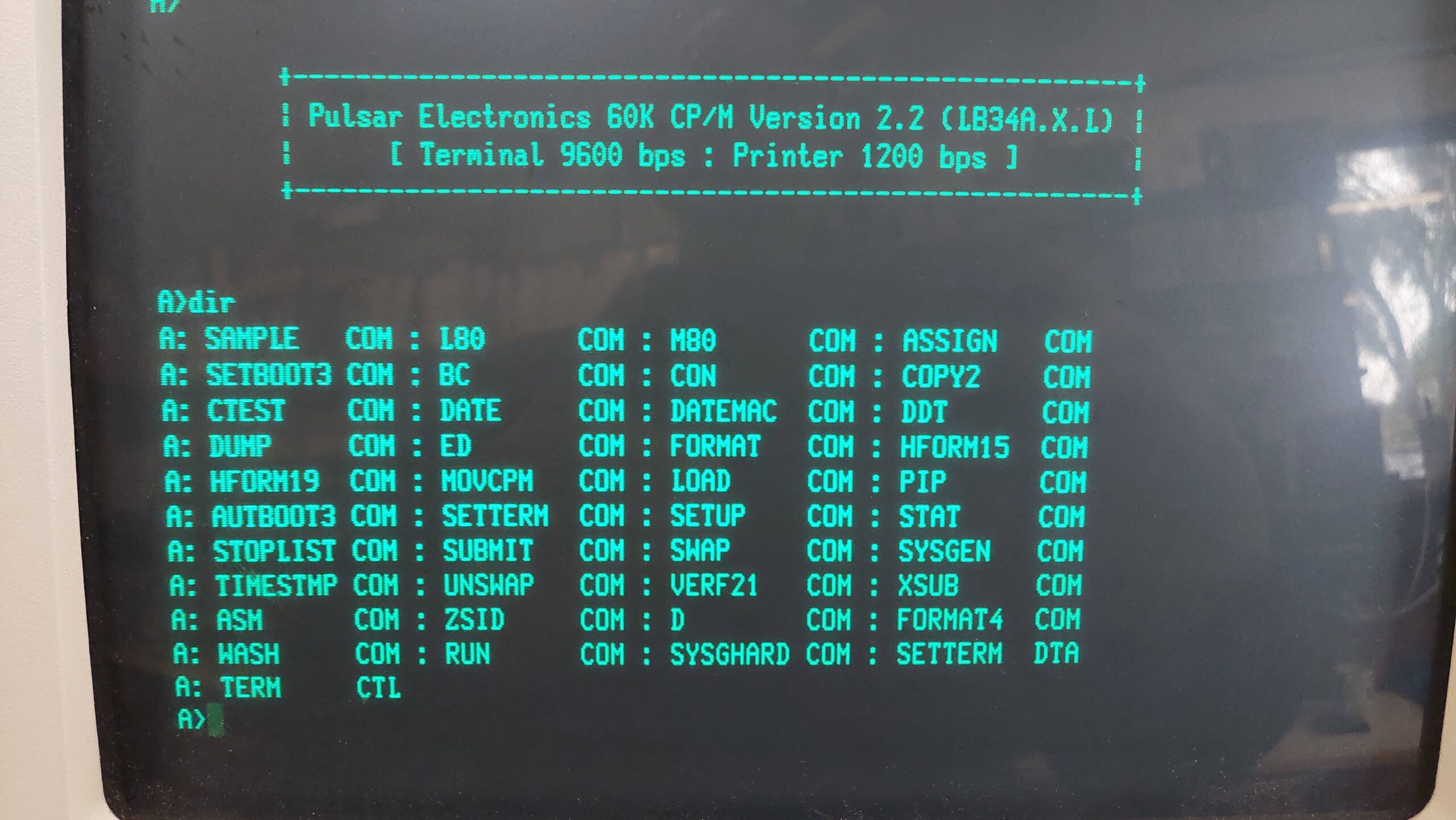
I was stunned and amazed to find that, on reset, the system booted from the hard disk, albeit with another serial communication cocktail: 9600 baud, 7 data bits, 1 stop bit, even parity.
Note that the system needs a floppy disk drive to be connected otherwise it will hang when checking for a boot disk in the floppy drive. If the floppy disk drive contains a bootable disk then it will take priority over the hard disk.
The hard disks are A to D and the floppy drives E and F. A directory listing of A: showed a bit of a mess really. I’ve encountered this before with SCSI2SD and Pulsar. It seems like the format program does not write E5 across the whole disk. In TurboDOS there is an ERASEDIR program that tidies this up but not so with CP/M. Instead, i created an E5 disk image on my PC, wrote it to the SD card using dd, and then rewrote the system track on the machine using SYSGHARD.COM.
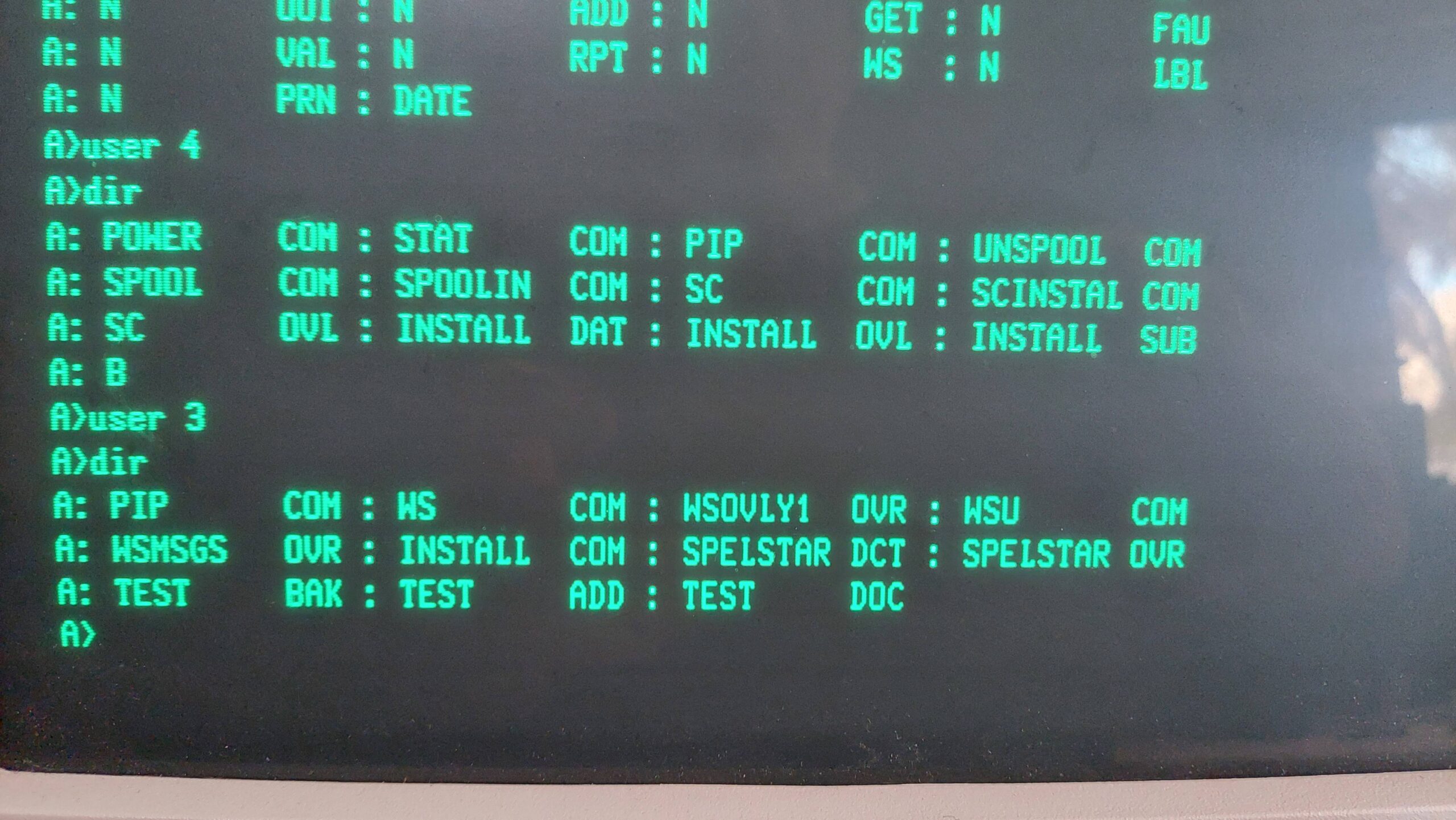
CP/M 2.2 supports user areas which can be used to quarantine different work environments. The implementation is not as slick as TurboDOS, which allows the user area to be used in much the same way as a drive letter. TurboDOS also maintains access to area 0 regardless of the current user number. And Turbodos has a copy program that allows files to be easily copied from one zone to another.
Without these features the first trick is to get pip into other user zones:
e> pip
*
e> a:
a> user 1
a> save 28 pip.com
Once it is in the zone the [G<user>] option can be used to pull in files from other zones eg zone 0 on floppy disks.
The hard disks have an 8kB block size, and with typical CP/M files being quite small, this wastes a lot of the available space.
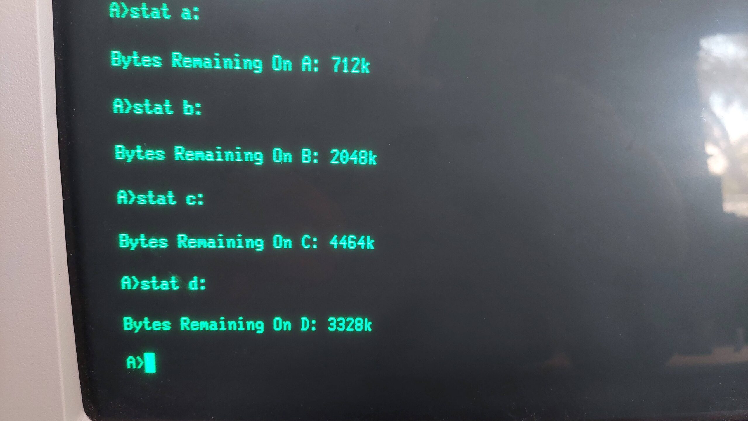
I set up the hard drive as follows:
User
A
B
C
D
Total
6616k
6616k
6584k
6552k
Remaining
576k
2048k
4464k
4376k
0
CP/M Utilities (103)
1
CP/M Setup (103)
2
Turbo Pascal (55)
3
Wordstar (21)
4
Supercalc (364)
5
Mbasic (66)
Games (89)
Voice Synthesiser
6
MT Pascal (47)
MT Pascal Support Files Development (49)
MT Pascal Gen Purpose Dev (50)
MT Pascal Programs (51)
7
DBASE II 2.4 (453)
8
Games (71)
9
Fortran (57)
Fortran Sources (393)
10
Cross Assemblers (8)
11
CBasic80 (63)
12
Cobol (64)
PLI (65)
13
14
15
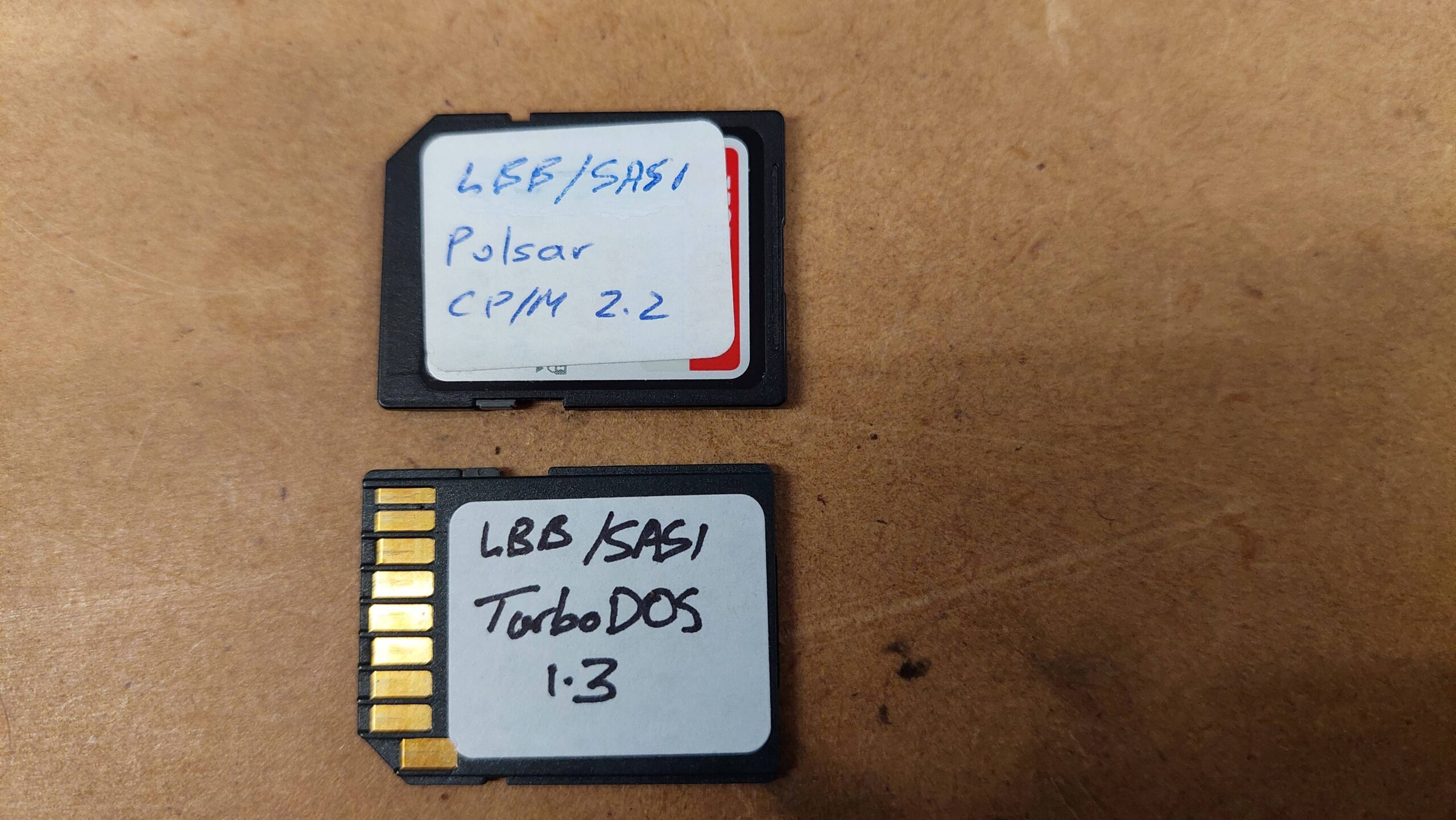
This system is now ready to go. Changing between TurboDOS and CP/M system is as simple as swapping over the SD Cards.
Note that most of the disk images that i have used are available from the Microbee Technology repository, or you can just contact me.
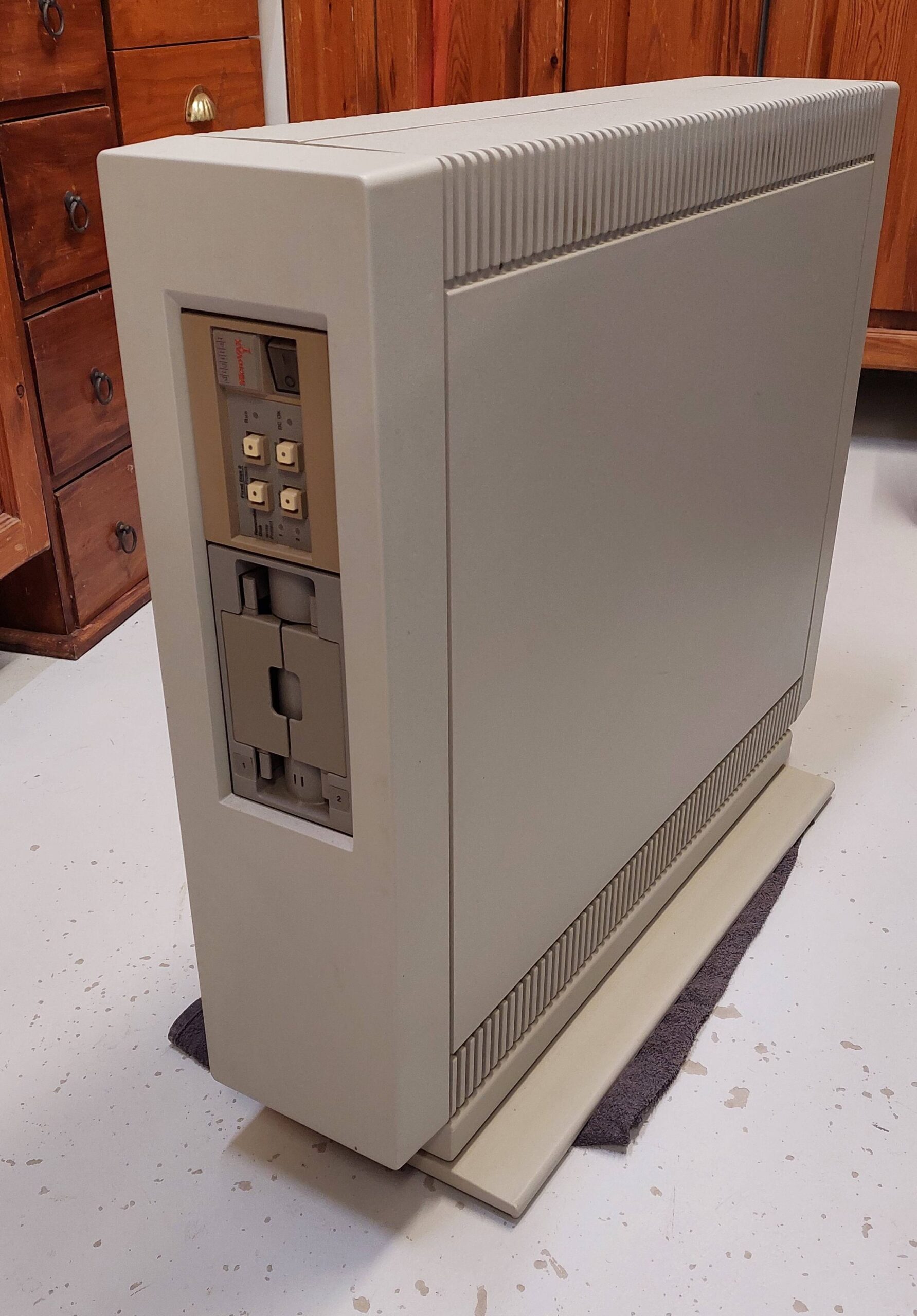
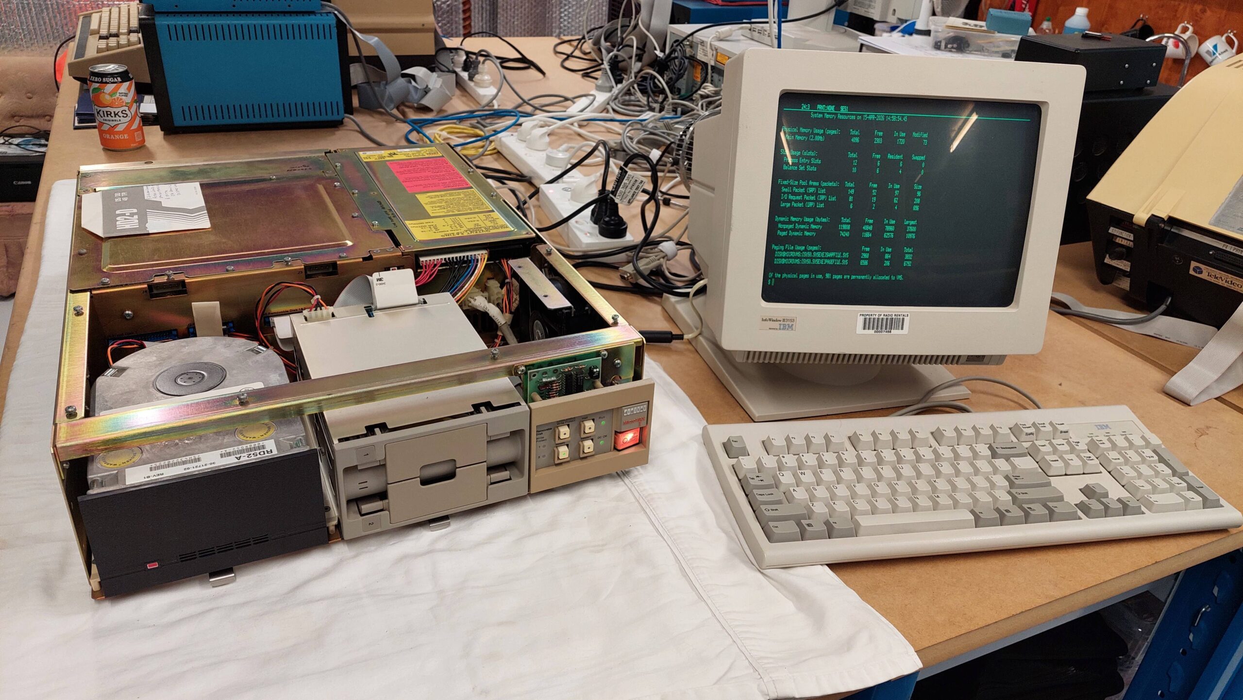
The subject of this site is microcomputers and although this unit has micro in the title it is actually a minicomputer. Why get hung up on consistency?
It belonged to a gentleman (Andrew C) who developed security software for the VMS operating system. I thought at first that this machine may have been a nostalgic purchase, but i am now convinced that this machine was used for development of software.
Curiously, it came with a bunch of tapes and a few high density 5.25″ disks none of which can be read by this machine.
The MicroVAX I was released in 1984 and was quickly superseded by the MicroVAX II which is a more common and more useable model.
The MicroVAX series was a more compact and less capable derivative of the VAX computers that i used as a student at Adelaide Uni in the early eighties, speaking of nostalgia.
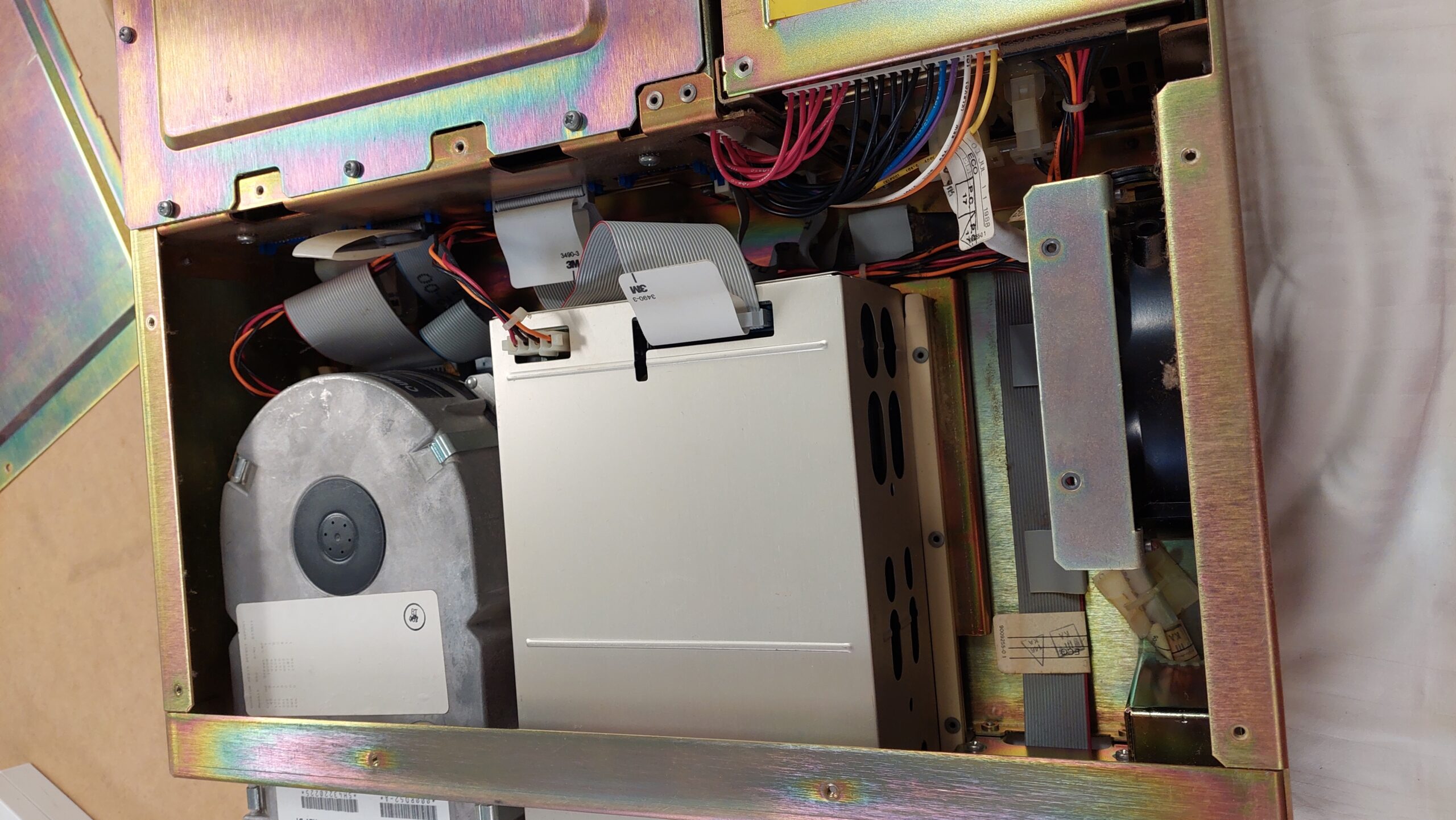
The MicroVAX I uses a Q-bus backplane which was also used in some DEC PDP computers. The CPU consists of two Q-bus cards. The MicroVAX I typically shipped with 1MB memory. This one has a dual floppy disk drive and a 30MB hard disk and would therefore have a floppy/hard disk controller.
With the only wired I/O being a serial line for a console terminal this unit is truly standalone. Additional Q-bus cards can be added for many other functions but i imagine they won’t be easy to find.
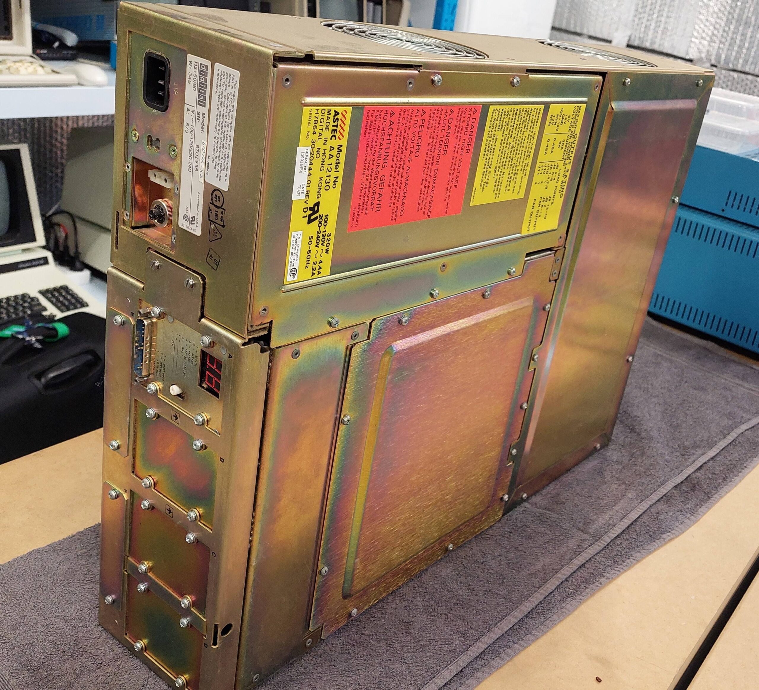
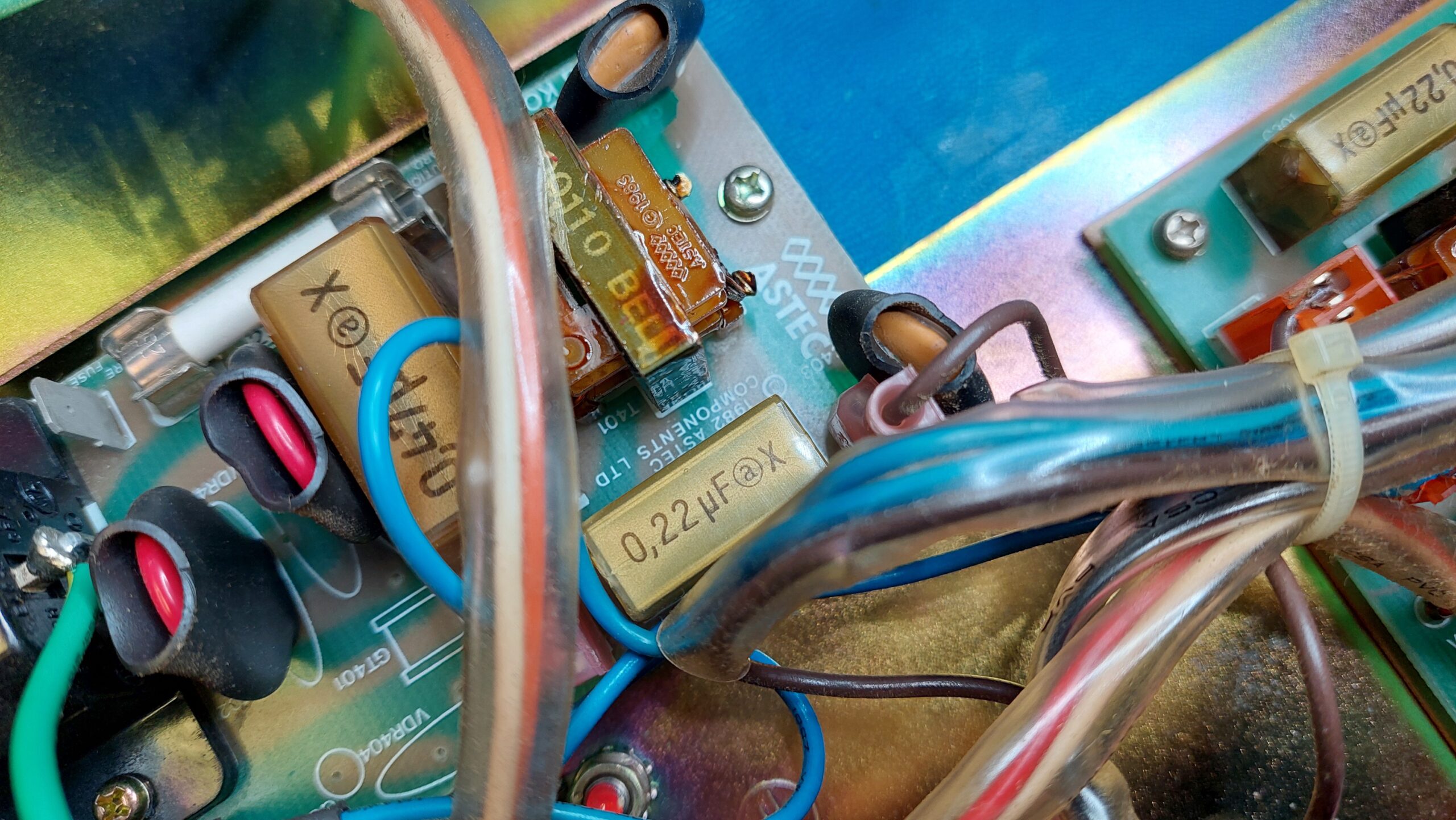
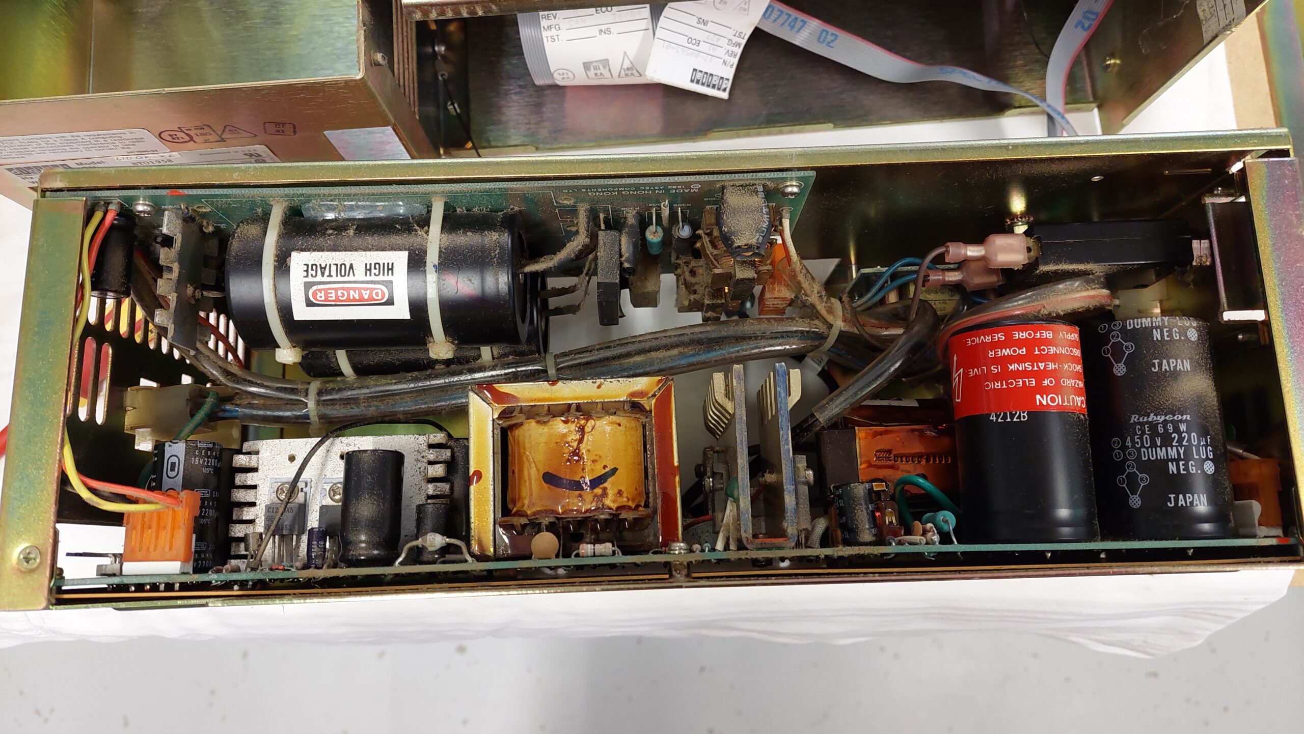
There are RIFA line filter capacitors inside, so there was work to be done before power could be applied.
I last used a VAX when i was a uni student in the early eighties. We used the vax to learn a little Fortran and a lot of Pascal. We also used it to run spice and graphical silicon design tools.
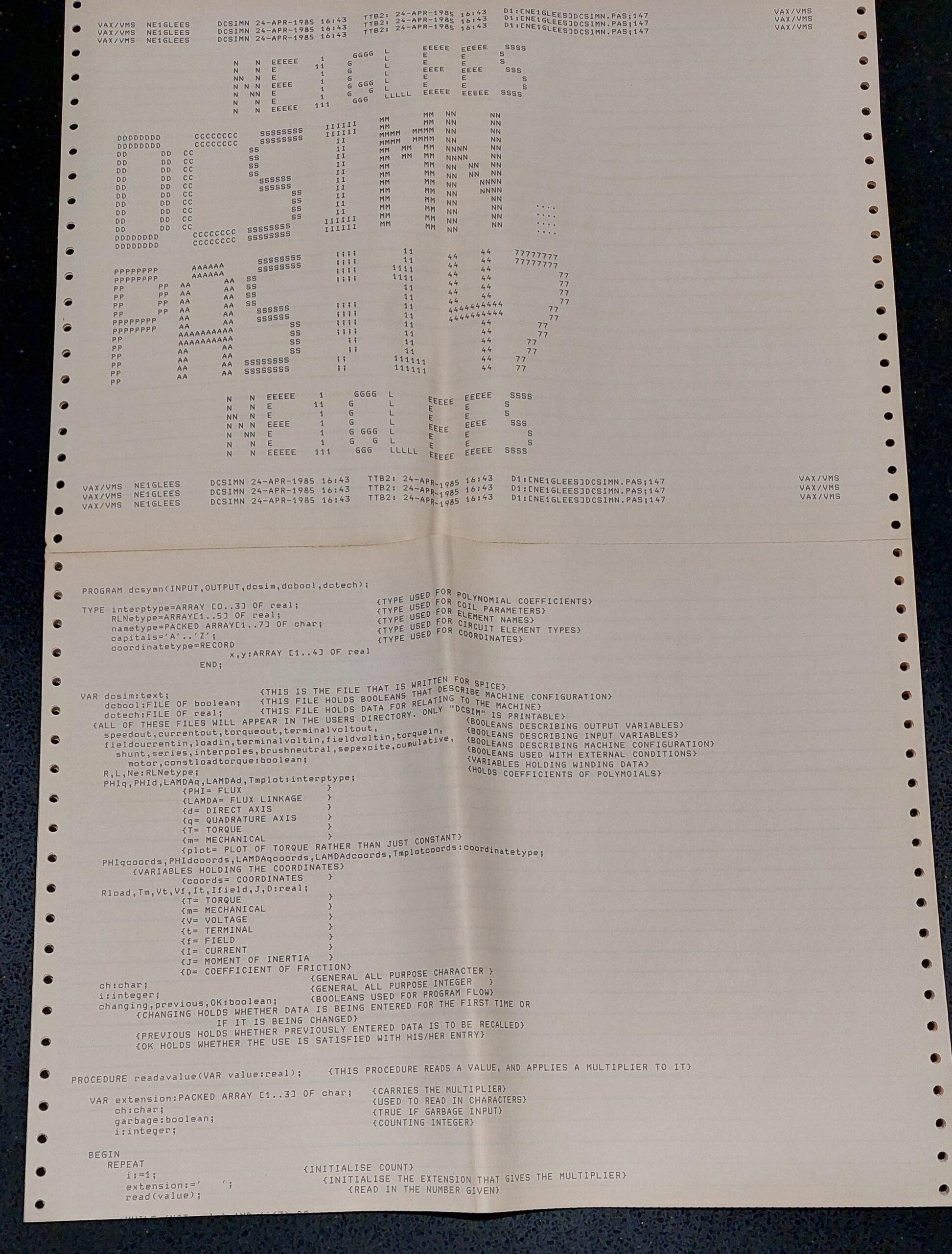
I kept a few souvenirs. This is a printout of a pascal program i wrote on a VAX in 1985.
My hope for this machine was that i might be able to get it to run a couple of compilers as a demonstration of what it could do.
This machine relies on a whole bunch of parts that i would struggle to repair or replace, so a huge investment in upgrades would be a significant risk.
The VAX/VMS ecosystem is not for the feint-hearted. VMS is both complicated and unlike more common system, the systems are often customised, the available documentation is incomplete, and the binary you want is never on the media that your machine can read. It turned out to be quite an adventure.
As usual, i have relied upon the good work of many other people who have taken the time to scan manuals, archive media, create emulators and other tools, and to post their experiences. I’ve tried to capture all those items in my posts although often the often anonymous individuals involved do not get the credit they deserve.
With two screws removed from the rear of the case the computer can be removed from its skin. The skin itself is very heavy and once gone the computer can be easily lifted on to a bench by two people.
The front panel comes off with the removal of several screws. The drives are on skids and can be released by pressing on the handles at the bottom of the case.
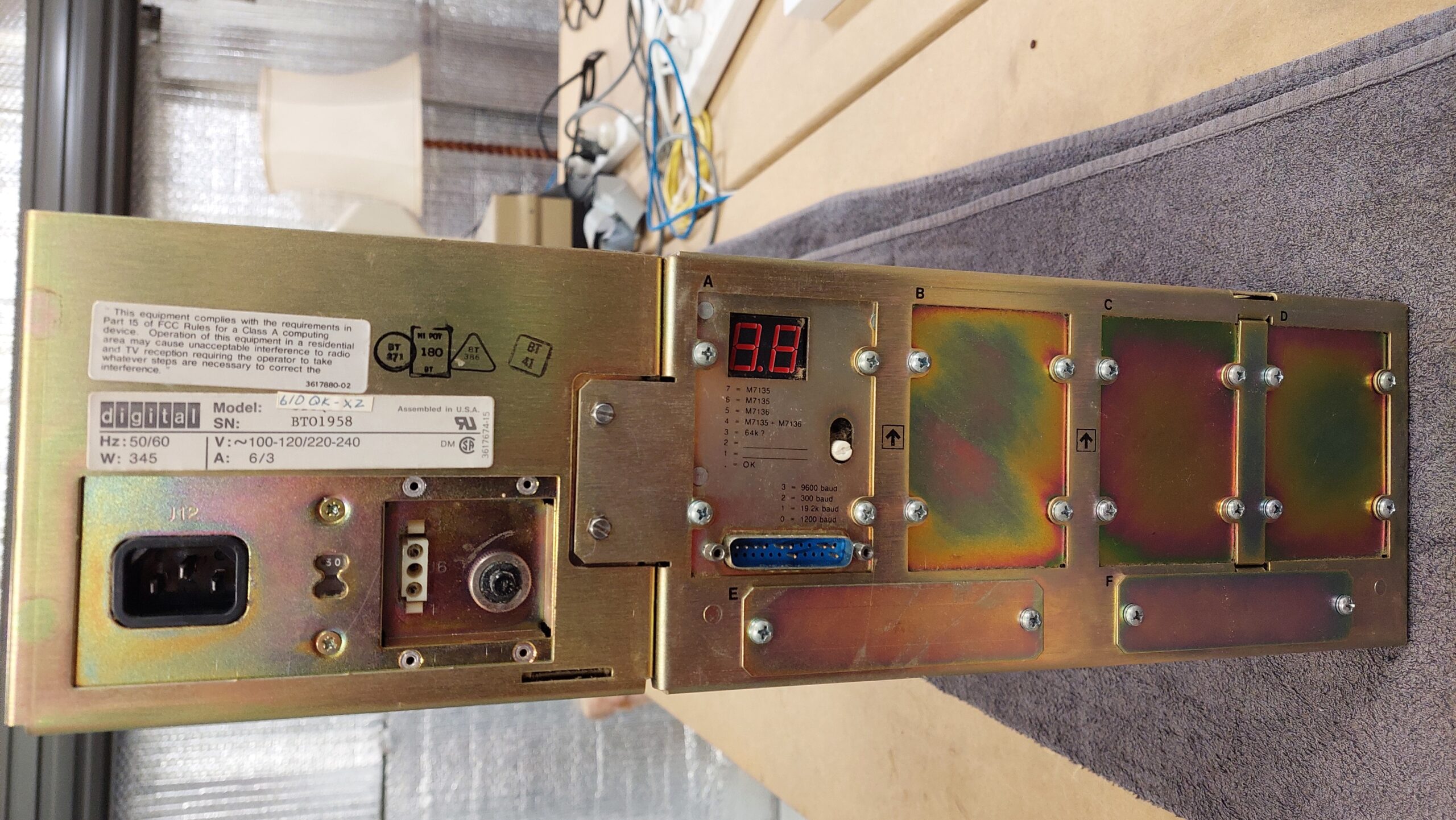
Two screws retain the back panel. Two ground leads need to be disconnected for the panel to be free and the rack to be revealed.
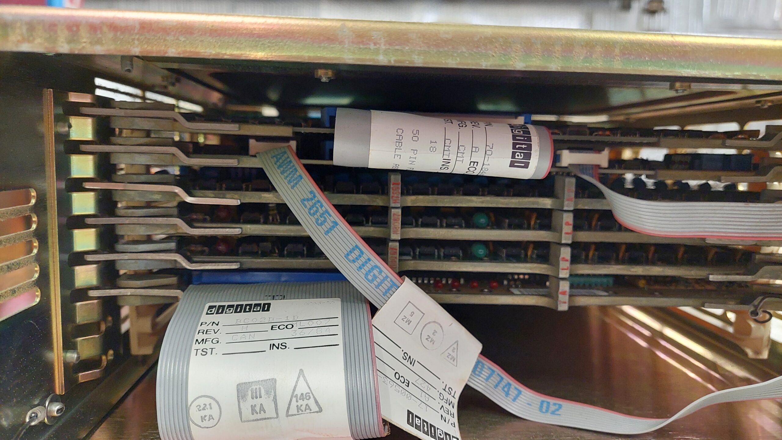
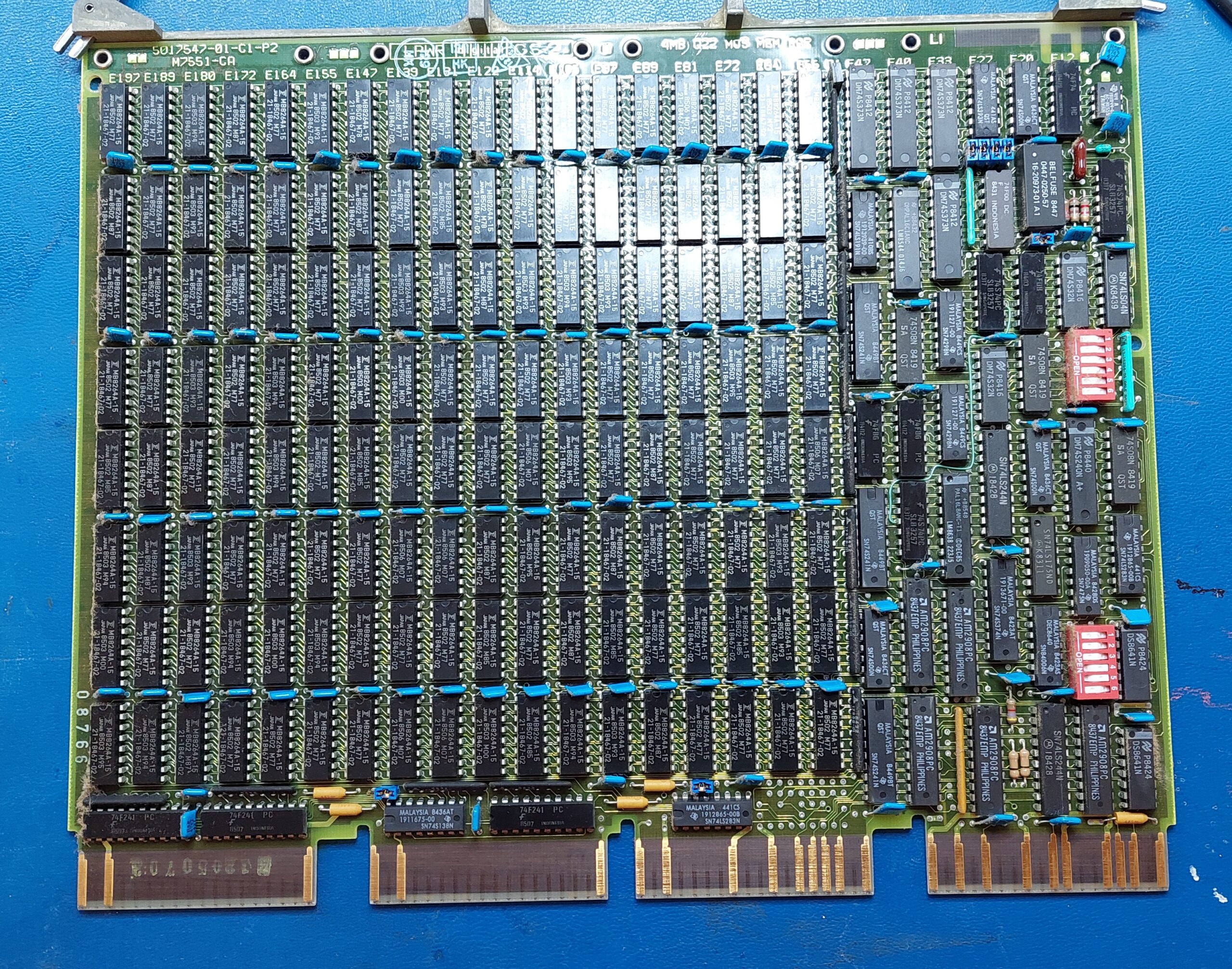
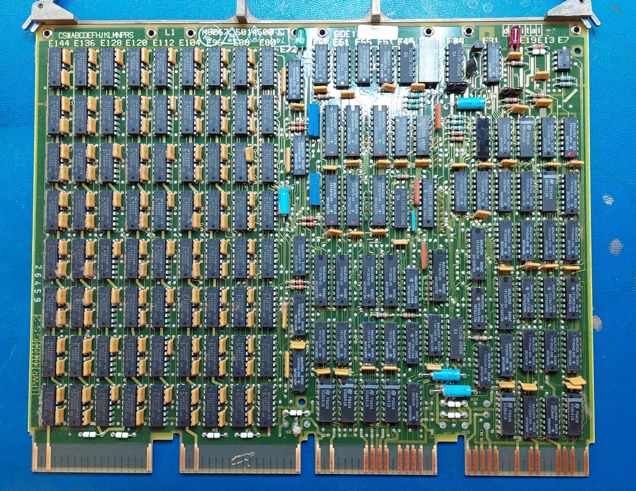
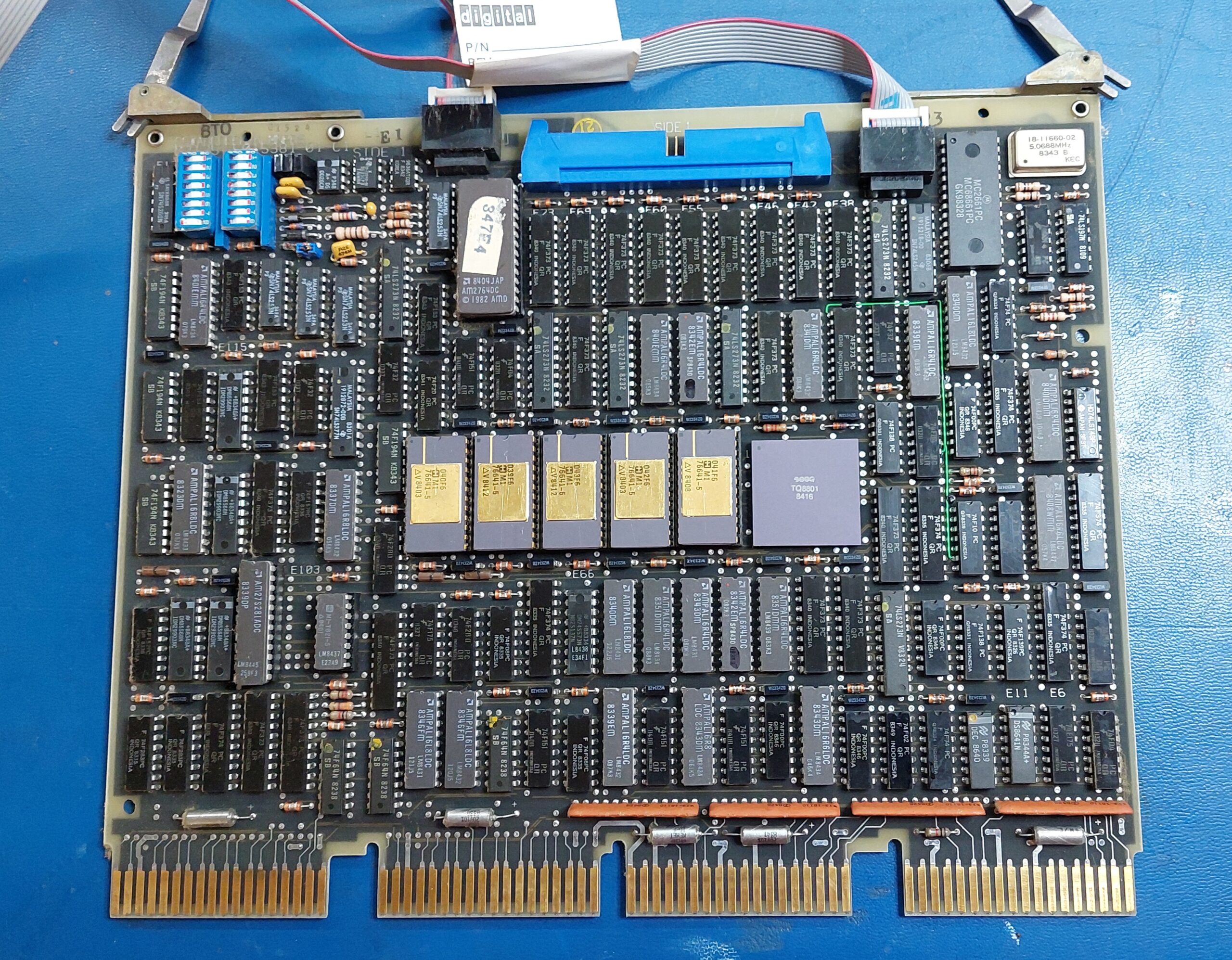
I pulled each of the cards for a photo and to confirm the ID. The ejection handles are solid and require a fair bit of effort to operate. They have to be positioned precisely when the cards are inserted into the rack. The levers pull the cards home.
The machine has:
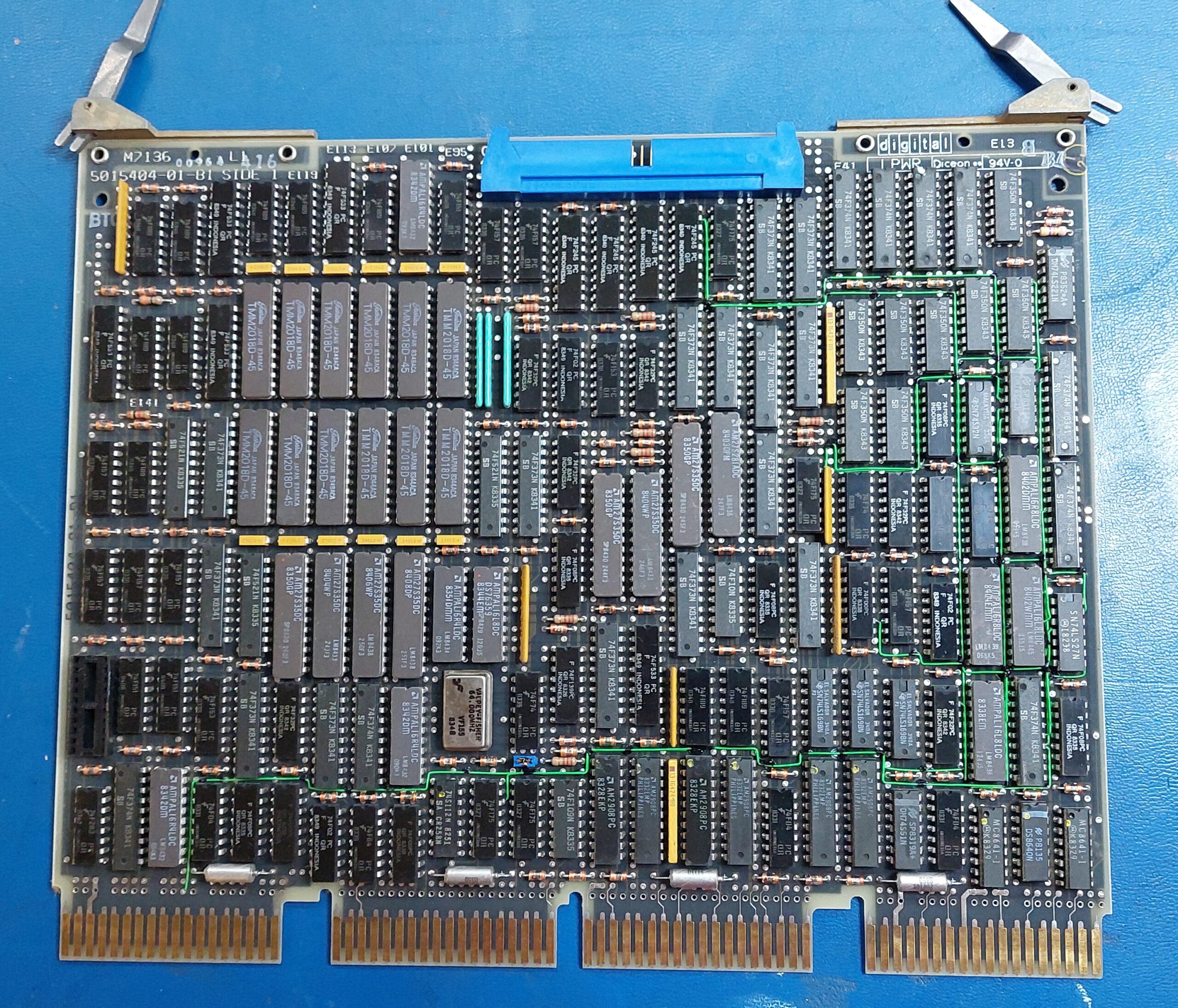
A KA610/KD32 CPU consisting of two cards M7135 Data Path Module and M7136 Memory Controller.
Memory modules including 1x M7551 MSV11-QA 1MB Memory Module and 2x M8067 MSV11-PL
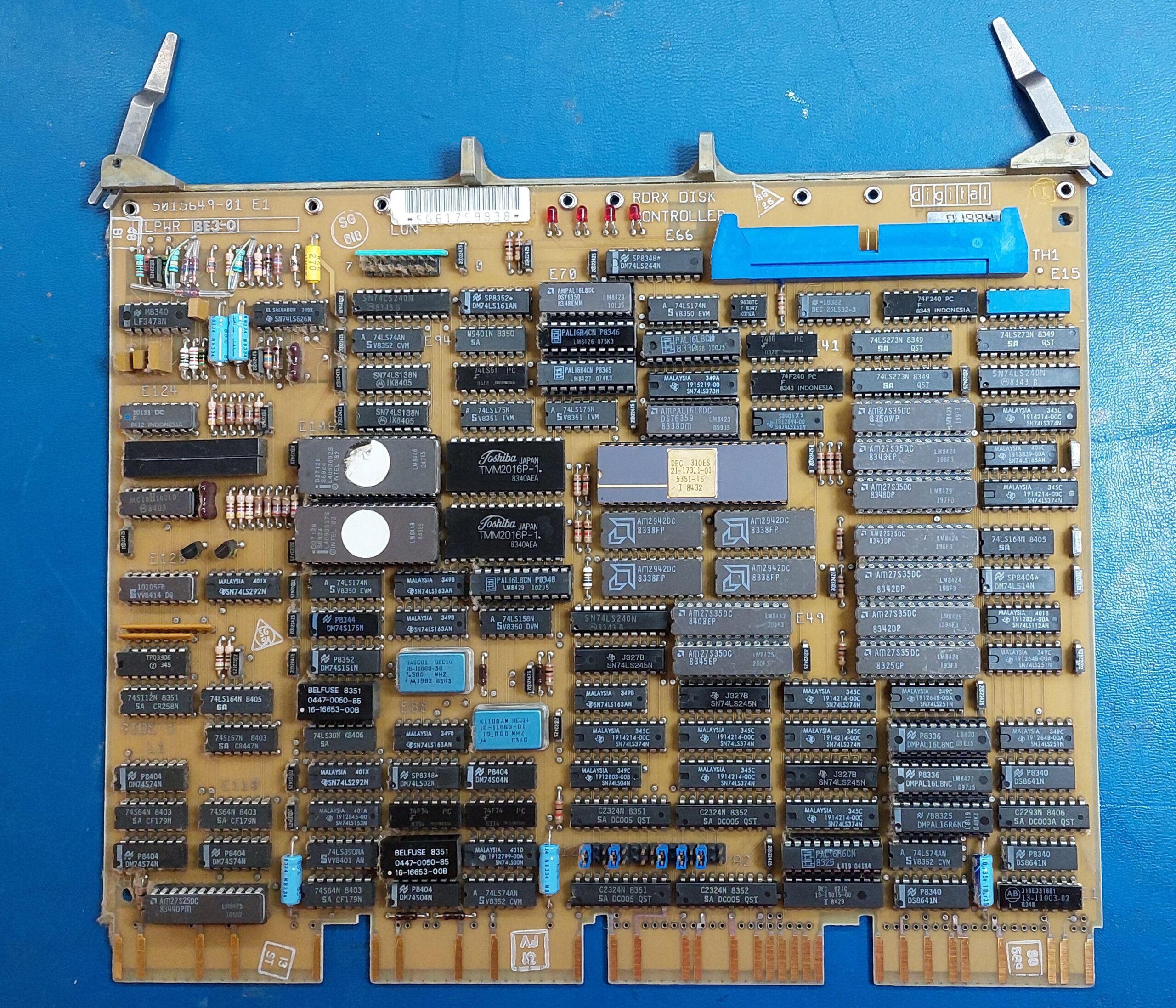
M8639 RQDX1 Disk Controller – not sure of version. Could also be RQDX2.
The only external I/O is the console serial port, so this is very much a standalone system. If it shows promise then i could acquire some additional cards.
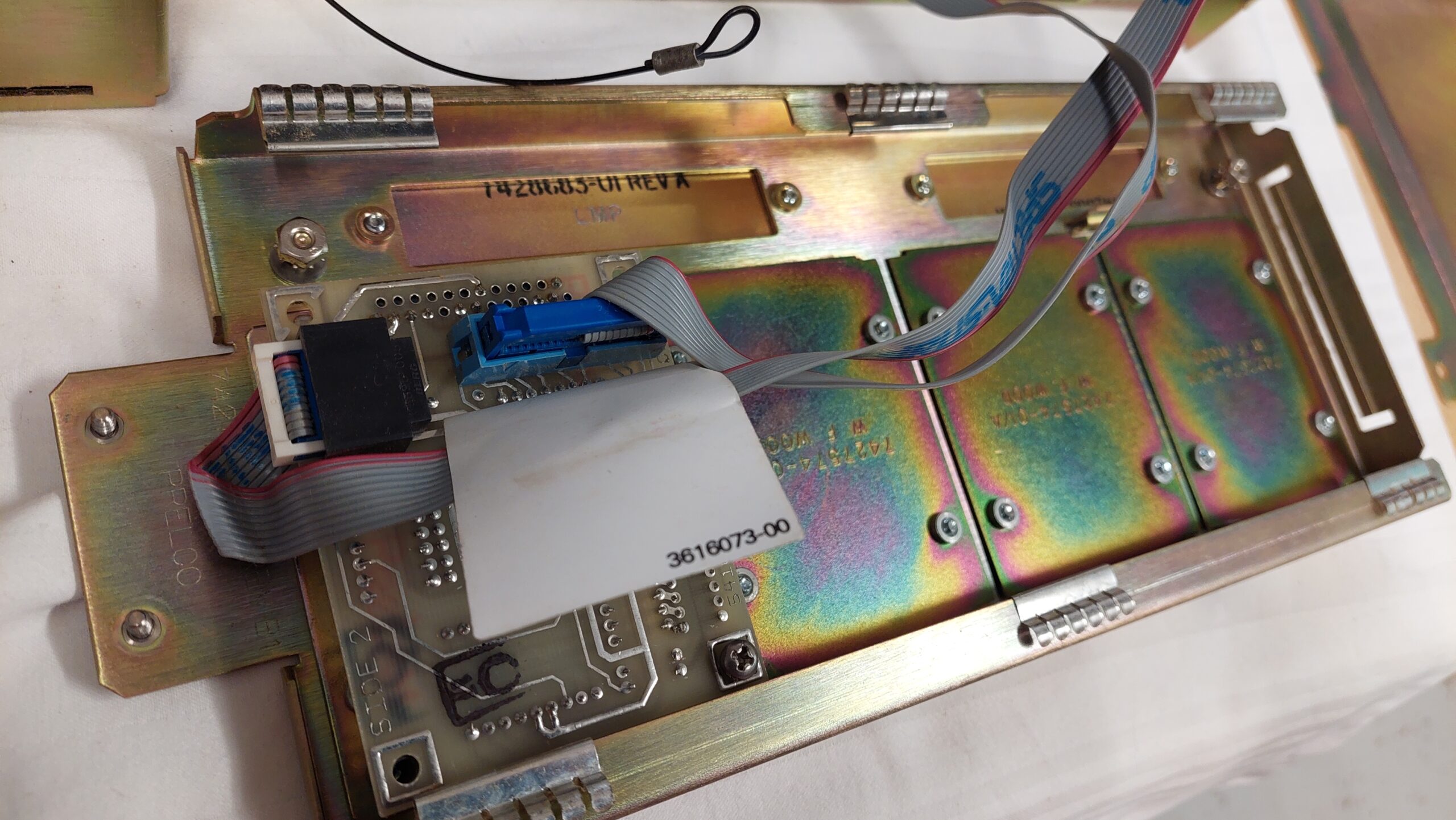
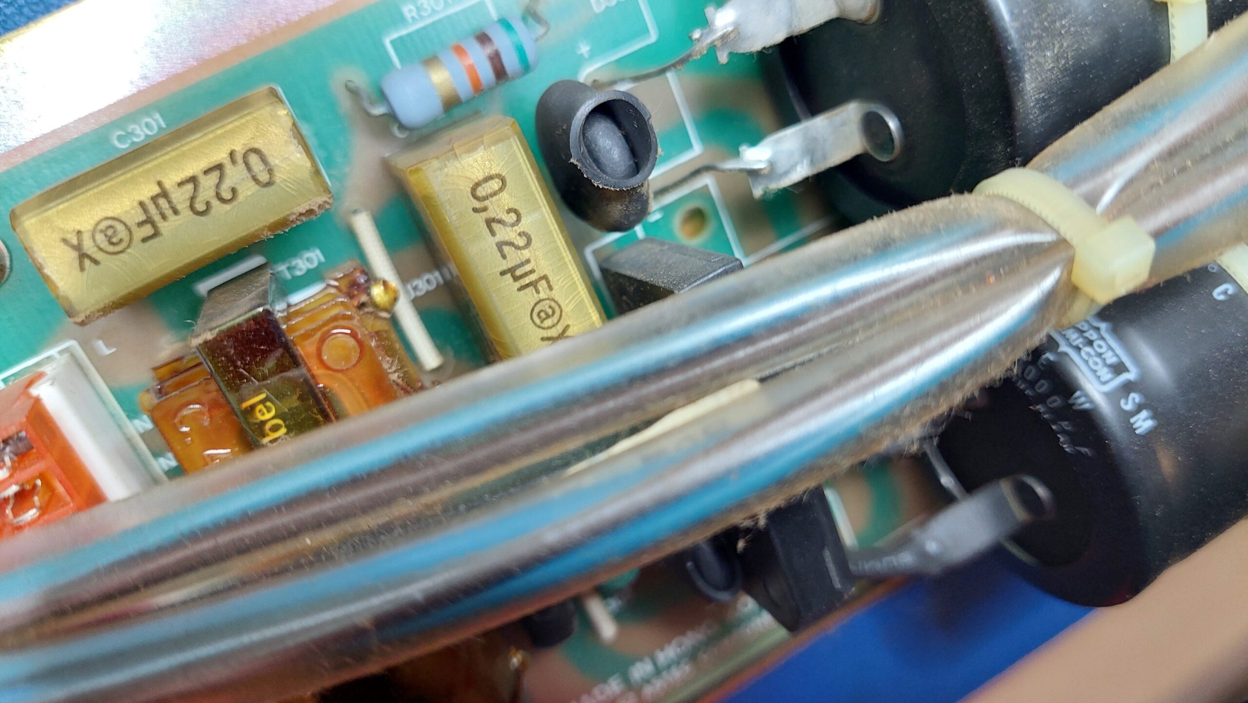
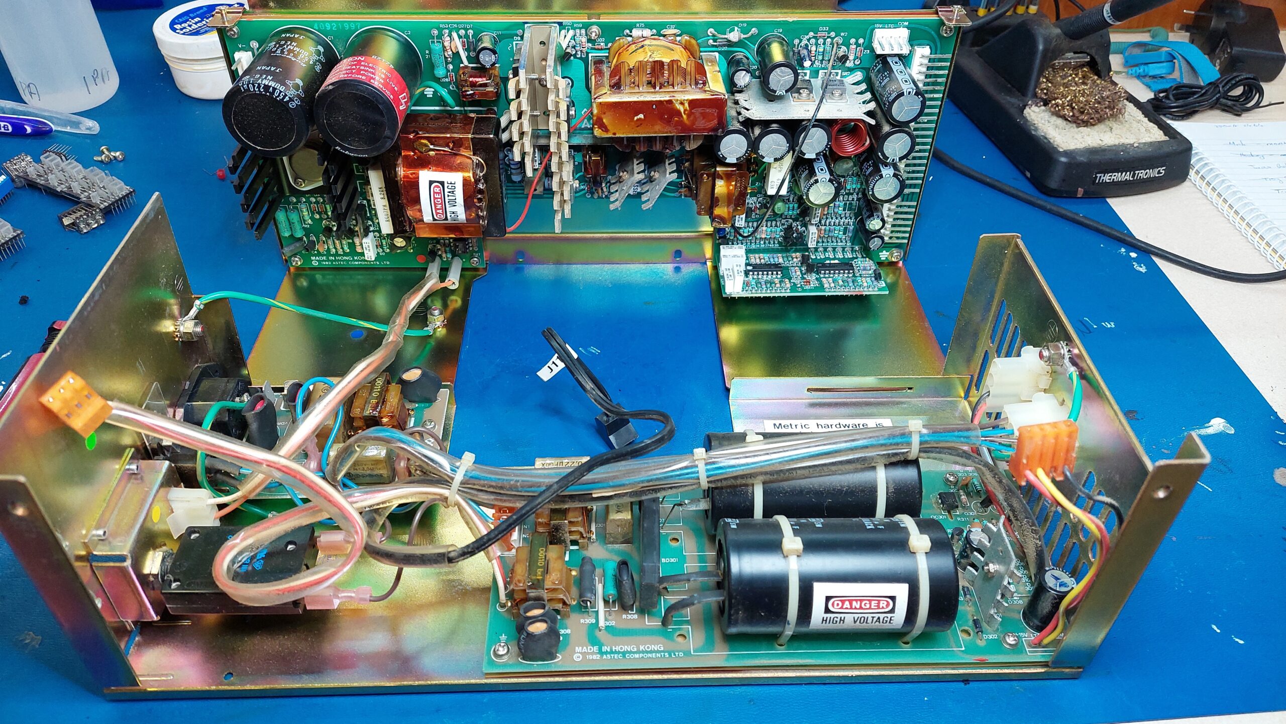
A few screws and some cable disconnections and the power supply is out. There are 4 RIFA line filtering capacitors and they were cracked as expected. There were no obvious issues with any other components.
I added the disk images and the ini file from the above link. Joy was had.
Attempts to use alternative disk and tape drives are somewhat frustrated by the limitations of the Microvax I, specifically the RQDX1 controller. There is no tape drive controller included in the Microvax I simh model. It may be possible to add one, but that is beyond my capabilities at present.
After replacing the line filter capacitors in the power supply i fired the supply up with a small load and checked the voltages. They seemed fine so i connected it up to the fans and some ide drives (just for supply checks) and that also looked good. A 3A dummy load was still required for the power supply to start.
Then i connected the backplane, and hooked up a terminal with VT100 emulation. The serial connection needs a null modem. On power up i was pleasantly surprised to see the unit sign on and the initial diagnostics passed – except that it gave an error 6 because there was no boot device.
I crossed my fingers and hooked up the hard disk and it booted up. Awesome.
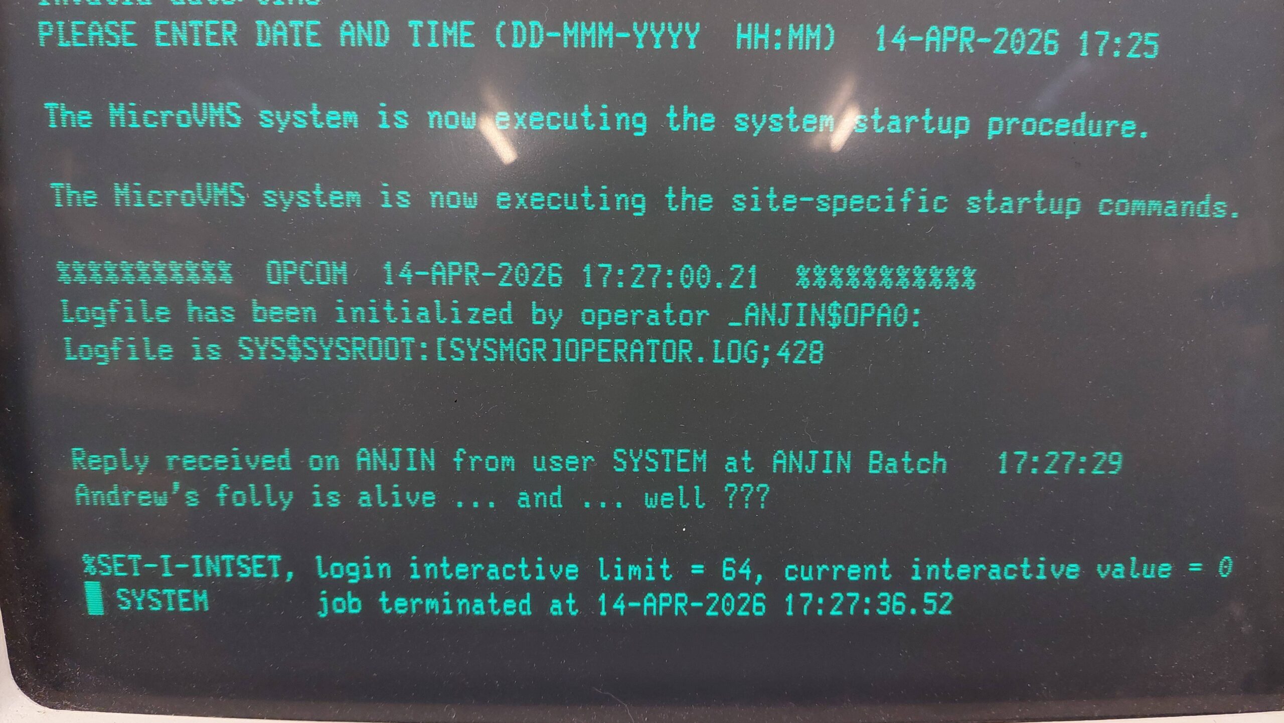
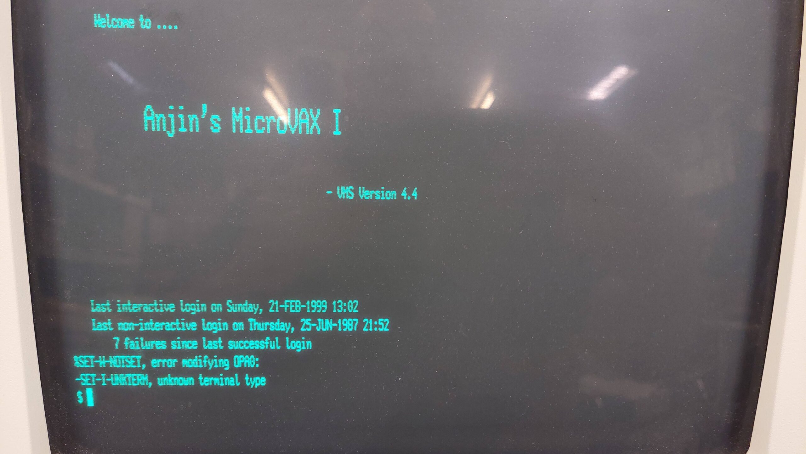
It was nice to see some humour from the previous owner in the startup message. The machine seems to be called ANJIN which i think relates to the company owned by the original owner.
There was a problem though – i did not have any passwords.
It is possible to reset the system password using a rather convoluted and only loosely documented procedure. There are several different versions of VAX machines and operating systems, and naturally commands evolved, so there was no obvious recipe. I had to experiment a little.
The first step is to enter a command boot mode. I found this worked:
Power on
Hit the halt button and then release. This gives the >>> ROM prompt.
Start the command boot mode with >>> B/1 0 (note the space)
A new prompt comes up SYSBOOT>
Parameters can be changed using the SET command. I have found limited information on these parameters. Initially i tried:
SYSBOOT> SET STARTUP_P1 "MIN"

SYSBOOT> CONTINUE
These settings are not cleared with a boot or power cycle. They have to be explicitly cleared from the SYSBOOT prompt or using the VMS SYSMAN program (see below).
This setting did have the effect of stopping startup scripts but i still could not log on.
With persistent googles i found a procedure that mentioned that an alternate user authorisation file (UAF) could be loaded.
The process is described in some detail in Sections 5.6 to 5.8 of “The OpenVMS Frequently Asked Questions(FAQ)”.
The default alternate UAF allows logon without a system password. The parameter is set as follows:
SYSBOOT> SET UAFALTERNATE 1

SYSBOOT> CONTINUE
After that i could log in with the system account and no password but i could not do a lot of things. I kept getting issues with library functions not being shared. The program that sets these attributes is called INSTALL. While reading about INSTALL i found that share status is reset on every boot so it is necessary to reshare them at startup eg with a script. This all relates to making sure that only validated code is executed by privileged programs. All this stuff is above my pay grade!
Eventually the penny dropped that the startup scripts that i’d disabled really need to be re-enabled because they are setting the necessary attributes. I retraced my steps and cleared the STARTUP_P1 parameter. That was much better.
I could have blown away the original UAF, but that could have had some unexpected consequences so i wanted to change the original. The program to change passwords is AUTHORIZE, but it really wanted to work on the alternate UAF.
More google and i found how to change AUTHORIZE to operate on the original UAF with the DEFINE command.
$ DEFINE/SYSTEM/EXECUTIVE_MODE SYSUAF SYS$SYSTEM:SYSUAF.DAT
$ RUN SYS$SYSTEM:AUTHORIZE
AUTHORIZE> MODIFY SYSTEM /PASSWORD=new_password
AUTHORIZE> EXIT
Once done, the UAFALTERNATE parameter can be set to 0 using SYSMAN (or via conversation boot):
$ RUN SYS$SYSTEM:SYSMAN
SYSMAN> PARAMETERS USE CURRENT
SYSMAN> PARAMETERS SET UAFALTERNATE 0
SYSMAN> PARAMETERS WRITE CURRENT
SYSMAN> EXIT
After a shutdown and reboot i had the original UAF with the new SYSTEM password and curiously a different login screen: