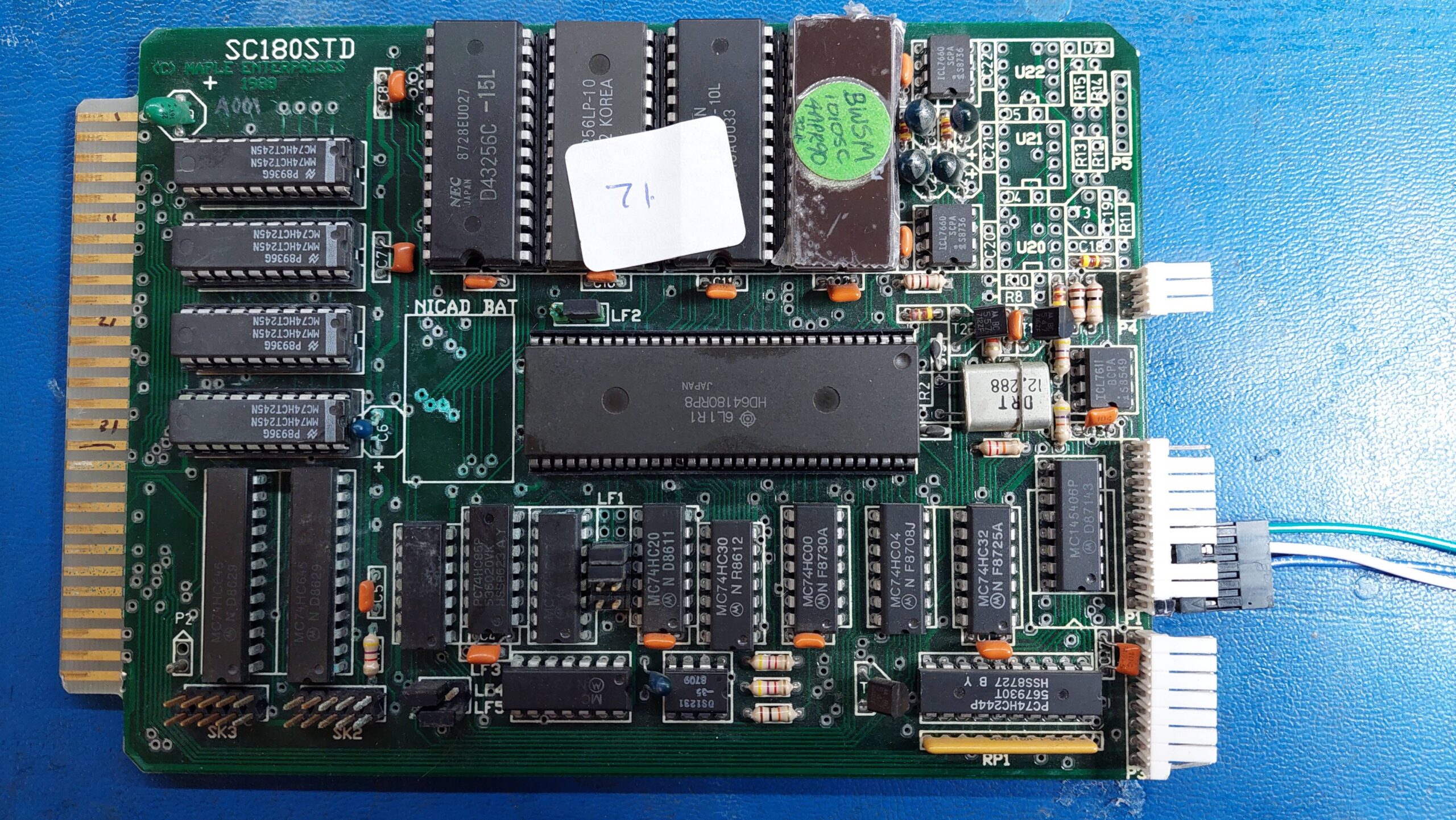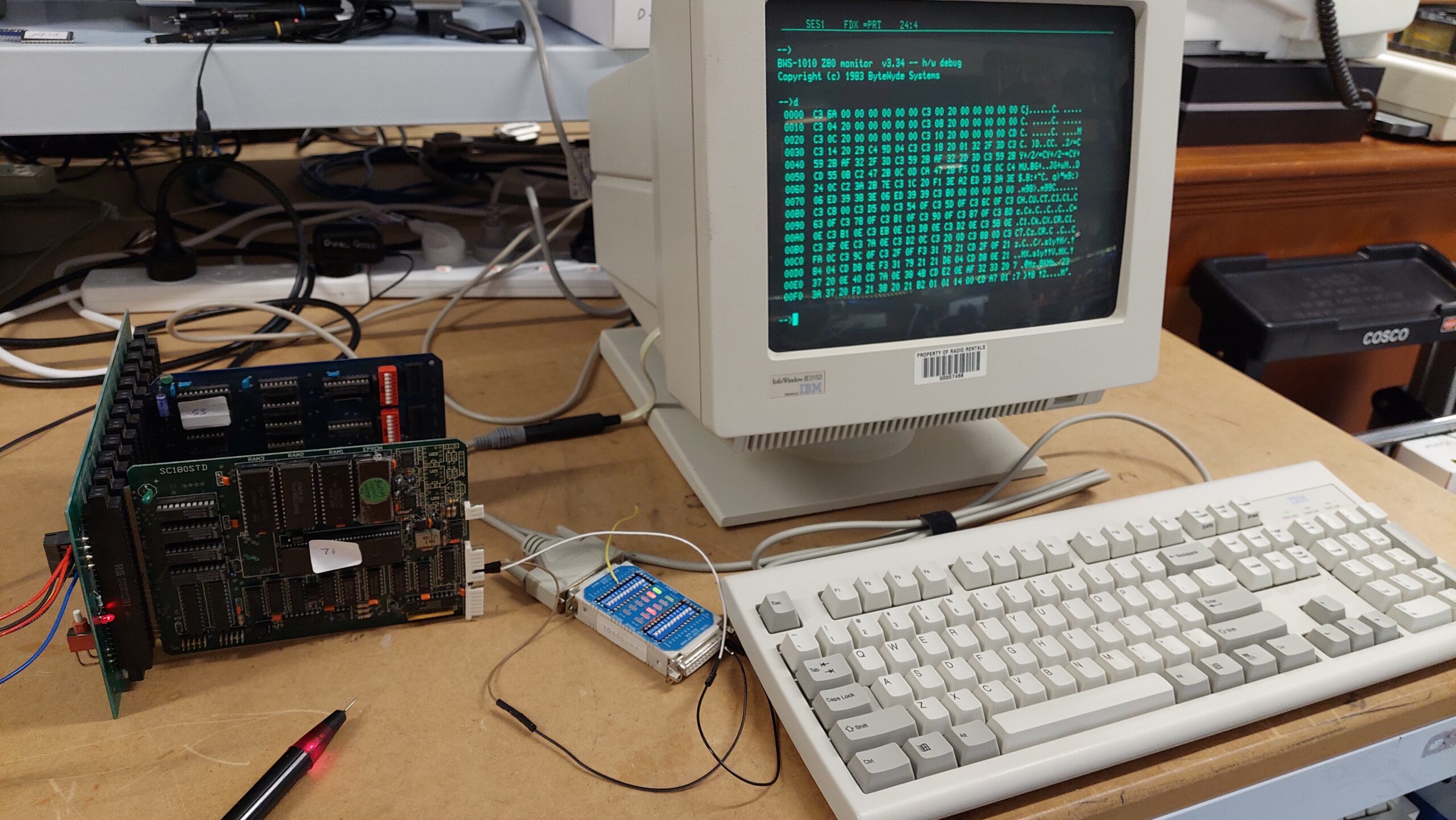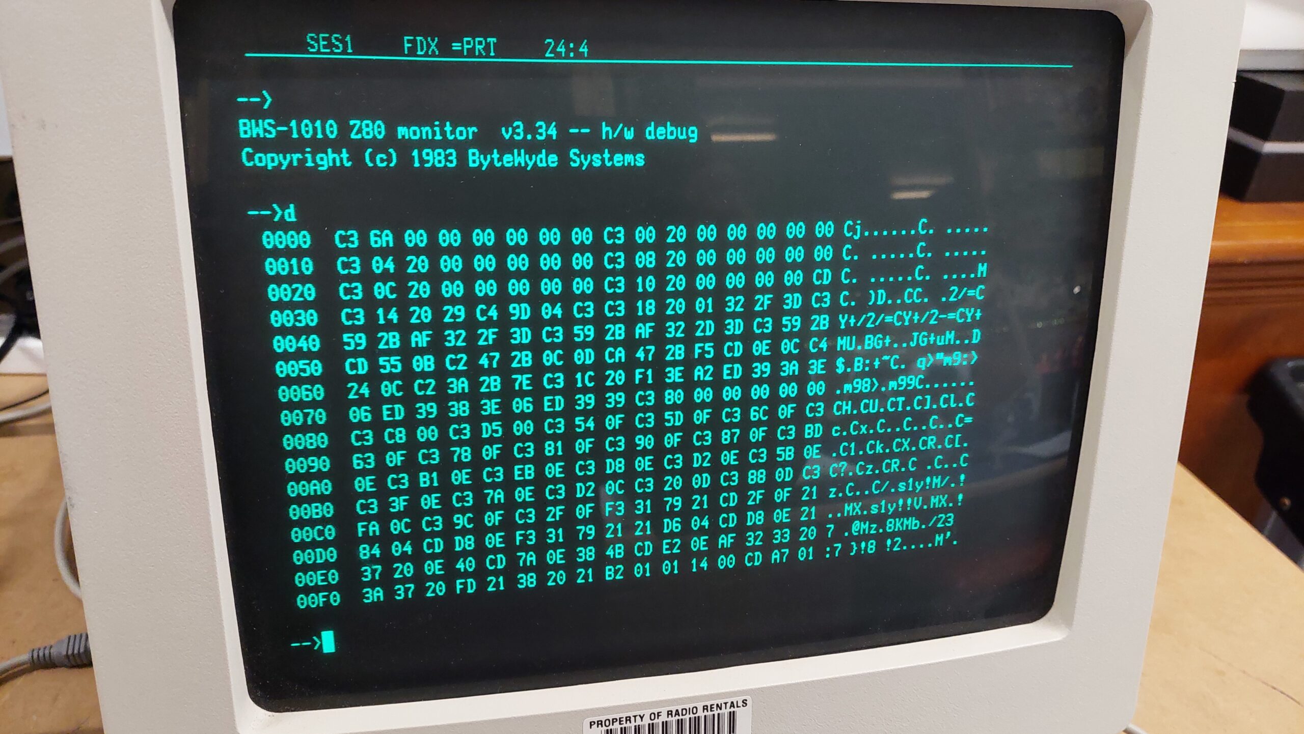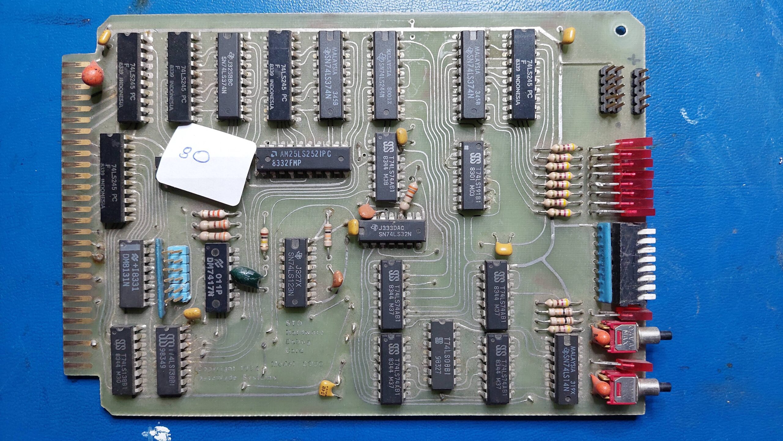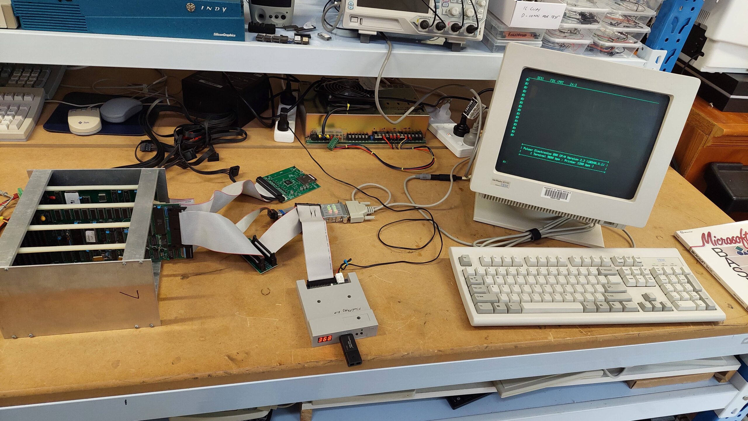
I have several machines based on Pulsar single board computers. A couple of these are running multiple processors and therefore require the capabilities of TurboDOS.
One that i have previously written about, the Little Big Board Computer, uses a single Little Big Board (LBB). This machine can happily run either TurboDOS or CP/M. It uses two 8″ floppy disk drives which gives it a generous 2.4MB of online storage which is pretty handy for CP/M – certainly better than the 280kB of storage that i had on my old Apple II clone back in the eighties. Nevertheless, after using the hard disk based TurboDOS systems it seems a little inadequate.
Another computer based on the LBB is the Pulsar 7500. This machine uses five LBBs with one as a master and the other four supporting one user each. Using an installation process similar to that used witht the 7500, i had previously set up an LBB with a SASI card, and had installed TurboDOS on a solid state hard disk as a single-user system. I used it to try out a Little Video Board. This is a perfect system for trying out a hard disk on Pulsar CP/M.
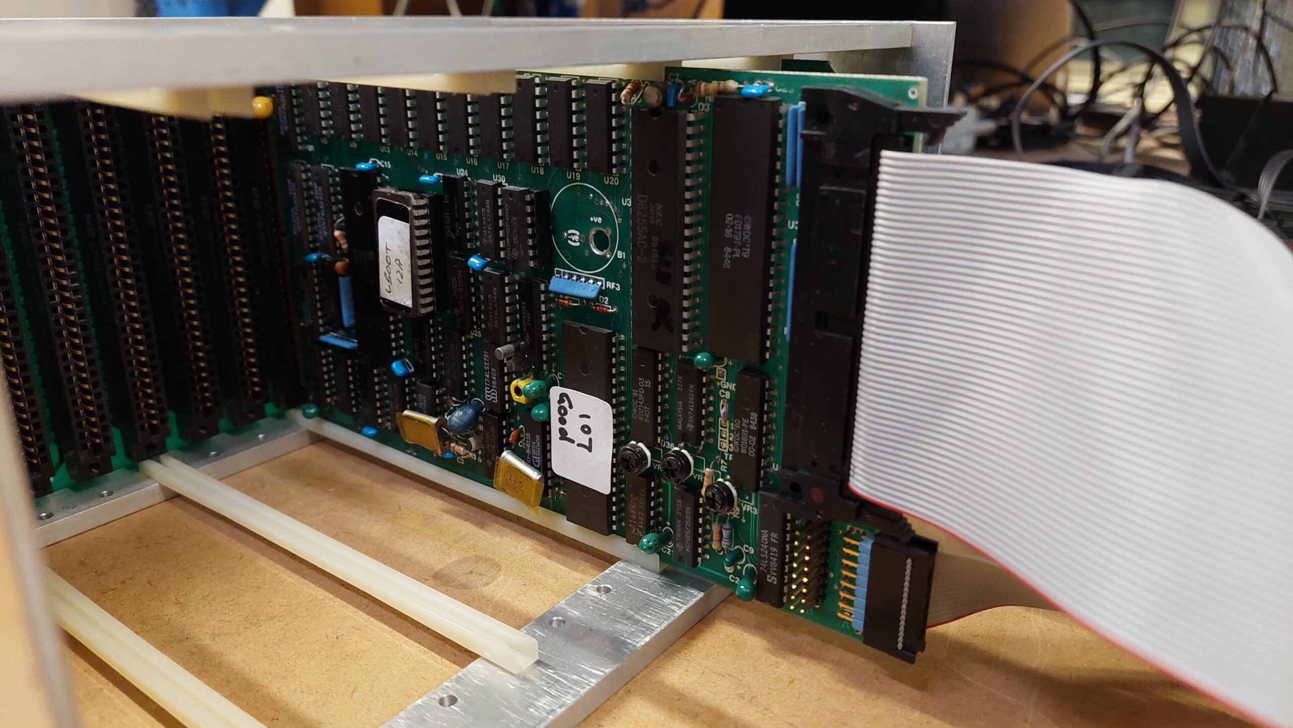
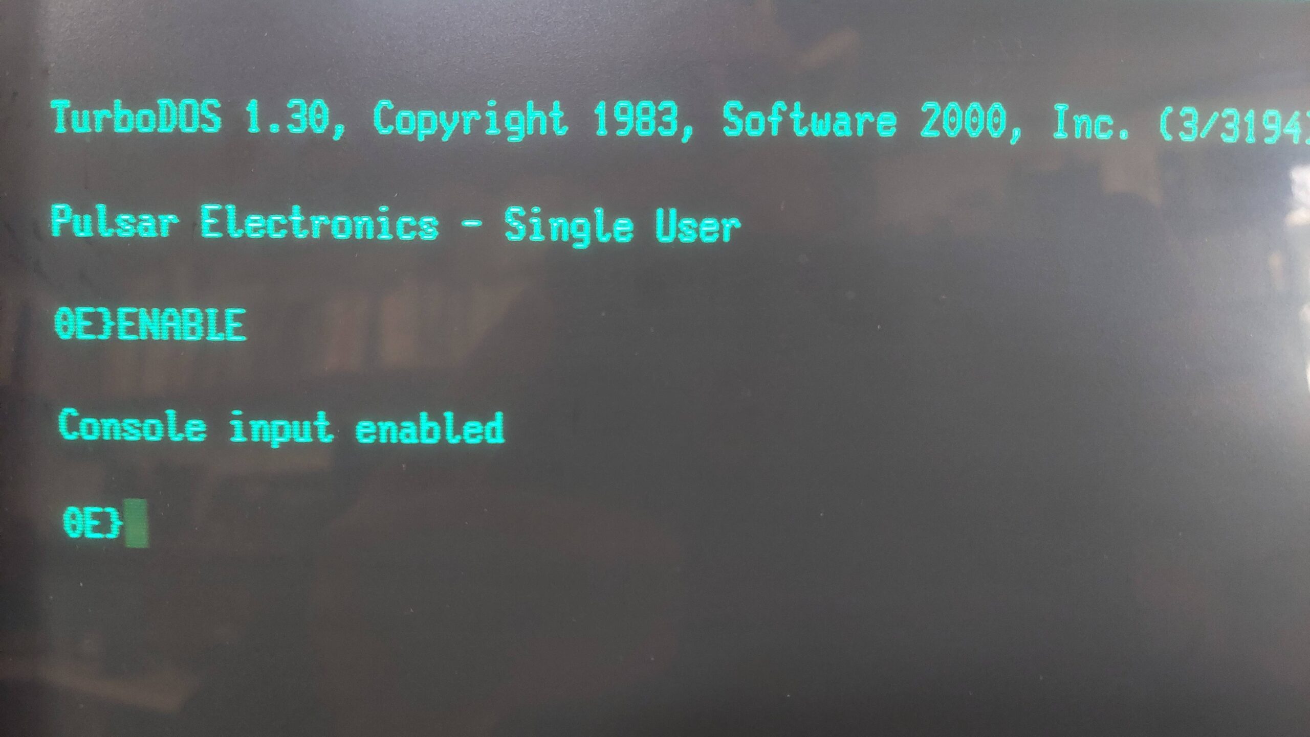
There were certainly hints that the Pulsar CP/M had hard disk support but how it all worked was clouded in mystery due to the absence of any Pulsar CP/M documentation. I’m sure it existed but i have never found any.
I figured that if the support was there, then it could be lurking on some 8″ Pulsar CP/M disks that had originated from the same source as the Pulsar hardware.
All of my 8″ disks have been imaged and, for most, the files have been extracted. This meant that i could run some searches using a modern PC and from there i could have a survey the various files of interest.
Out of the 115 viable Pulsar CP/M disks i found 6 that had a program called hform, which isounds a lot like a hard disk formatter.
One of these disks, 103, was labelled “Pulsar CP/M 2.2 (Update 6) CP/M 2.2 Configuration Disk”. It contains a lot of assembler files, library files (includes), and some scripts. There was also a file called note-32 and that contained a lot of useful instructions on how to build a hard disk CP/M system for the LBB.
Contents of notes-32
                NOTES ON ASSEMBLY OF PULSAR BIOS

         A new utility called 'ASSIGN.COM' has been provided.
         This allows any drive to be swapped with Drive A:.
         This permits programs such as copy to work
         correctly even when booting up from the hard disk
         which normally signs on as Drive A: when hardboot
         is selected. (Note that the hard boot loader and
         hard boot prom must be used when the hardboot
         option is selected.

         Also another utility called 'STOPLIST.COM'. This is
         used when you wish to abort the buffered print mode
         (otherwise you may have to wait for up to 63k of
	 buffered print to finish) when using the RAM card
	 buffer.

	 A utility called 'CON.COM' has also been added.
	 This displays the current configuration of your
	 BIOS.


     1.   Set switches in CPMSYS.LIB for the following :

          - Hard disc present  (HARD : true/false)
          - Hard disc split into up to 4 drives  (NUMHARD : 0..4)
          - Reserve hard disk boot tracks  (HBOOTRAK : true/false)
          - Boot from hard disc            (HARDBOOT : true/false)
          - Large hard disk directories    (LARGEDIR : true/false)
          - Virtual RAM disc present (VDISC : true/false)
          - Printer buffer present up to 63K  (PRINTBUF : 0..63)
          - Number of RAM cards (RAMCARDS : 1/0)
          - Floppy interface side select line used
                                   (SIDESEL  : true/false)
	  - Large directory on floppies  (EXPDIRF : true/false)
				only works if SIDESEL is true

	  [ If sidesel is true then LBB can control up to 4
         double-sided drives but cannot read old dual-directory
         disc format since hardware won't read address marks
         with side field = 0 while side select line active ]

         CAUTION: If using hard disk in system, and you change
         any parameters (large directory, boot tracks or
         split operation) then you should FIRST back up your
         hard disk, re-format it, change the system and copy
         back your files to the hard disk !

	 ****************************************************
	 *						    *
	 *  Format4 must be used with a side select system. *
	 *						    *
	 ****************************************************

     2.   If generating a hard disc system set switches in
          CPMSYS.LIB for the following :

          - Xebec or DTC controller (XEBEC : true/false)
          - Make/model of hard disc drive (set only one true)


     3.   Set switch in CPMSYS.LIB for the following :

          - Slow or fast floppy drive step rate
          (SLOWSTEP : true/false i.e 10 or 3 msec track to track)


     4.	  - The bios version part of the sign-on shows you which
	  flags have been set.

 	  - normal bios		(LB31A...D)
	  Slowstep=false, Hard=false, Ramcards=false, Sideselect=false

   	  - custom bios		(LB31ASHML)
	  Slowstep=true, Hard=true, Ramcards=true, Sideselect=true

     5.   Assemble your new bios :

	  e.g.  M80 =$1
          	L80 $1/N,$1/M/X/E

        Note that some later versions of L80 (e.g. 3.44)
        have been found to be unsuitable as they load
        hex from from address 100h instead of the stated
        origin (e.g. bios)

        Take note of which submit file & parameters to use.
        (E.g. use ctrl-P to print if possible)

        Assemble the loader indicated during bios assembly.

        Generate the CPMXX system image indicated using MOVCPM.

     6.   Link your bios with it's loader and CP/M .

          - For 62K floppy boot systems SUBMIT DGEN62 LBLDR9 LB31A
          - For 61K floppy boot systems SUBMIT DGEN61 LBLDR10 LB31A
          - For 60K floppy boot systems SUBMIT DGEN60 LBLDR11 LB31A

          - For 61K hard boot systems SUBMIT HGEN61 LBHLDR10 LB31A
          - For 60K hard boot systems SUBMIT HGEN60 LBHLDR11 LB31A

          DGEN62.SUB
          ;use: submit dgen62 <loadername> <biosname>
          ;inputs: loadername.hex, biosname.hex, cpm62
          ;xsub.com, zsid.com  must be on default disc
          ;creates system file biosname for sysgen
          XSUB
          ZSID
          ICPM62
          R180
          I$1.HEX
          R880
          I$2.HEX
          R
          G0
          SAVE 50 $2
          ;PLEASE REBOOT ... SYSGEN DOES NOT RUN UNDER XSUB

          HGEN61.SUB
          ;use: submit hgen61 <loadername> <biosname>
          ;inputs: loadername.hex, biosname.hex, cpm61
          ;xsub.com, zsid.com  must be on default disc
          ;creates system file biosname.hrd for sysghard
          XSUB
          ZSID
          ICPM61
          R180
          I$1.HEX
          R880
          I$2.HEX
          R
          G0
          SAVE 54 $2.HRD
          SYSGHARD
To add a hard disk I had to reconfigure and rebuild the CP/M BIOS. I’d never done that before so i figured it would be an adventure.
The file CPMSYS.LIB (an ASCII file) contains parameters for the BIOS including the hard drive, controller type, and SASI interface type. In the early eighties hard drives typically had a ST506 interface (often referred to incorrectly as an MFM interface). To convert these drives to SASI (the original name for the SCSI interface) a controller, eg an Adaptec ACB-4000 was required.
Although i have several of the Adaptec controllers, practically it is far easier to emulate a SASI/SCSI drive eg with a SCSI2SD than it is to find a viable ST506 compatible hard disk. I have already used SCSI2SD on other systems to emulate an Adaptec controller and companion disks. TurboDOS, for example, will boot from a SCSI2SD on an LBB so i’m hopeful that the same setup will work for CP/M.
I generally try to use the largest hard disk that the BIOS and Formatter will support. The latest formatter on Disk 103 is HFORM19. It supports many hard disks from the period, the larger ones of which are:
- CDC 9415-5 Wren (5 surfaces) 31.3MB
- Disctron D526 20MB
- Rodime 204 Series 23.1MB
The CDC 9415-5 Wren is a little confusing because there are two sizes. The 31MB version has 3 “disks” and 5 surfaces and the smaller unit has 2 disks and 3 surfaces, whereas the CPMSYS.LIB file refers to 2 or 3 platters which i think must be the same as a “disk”.
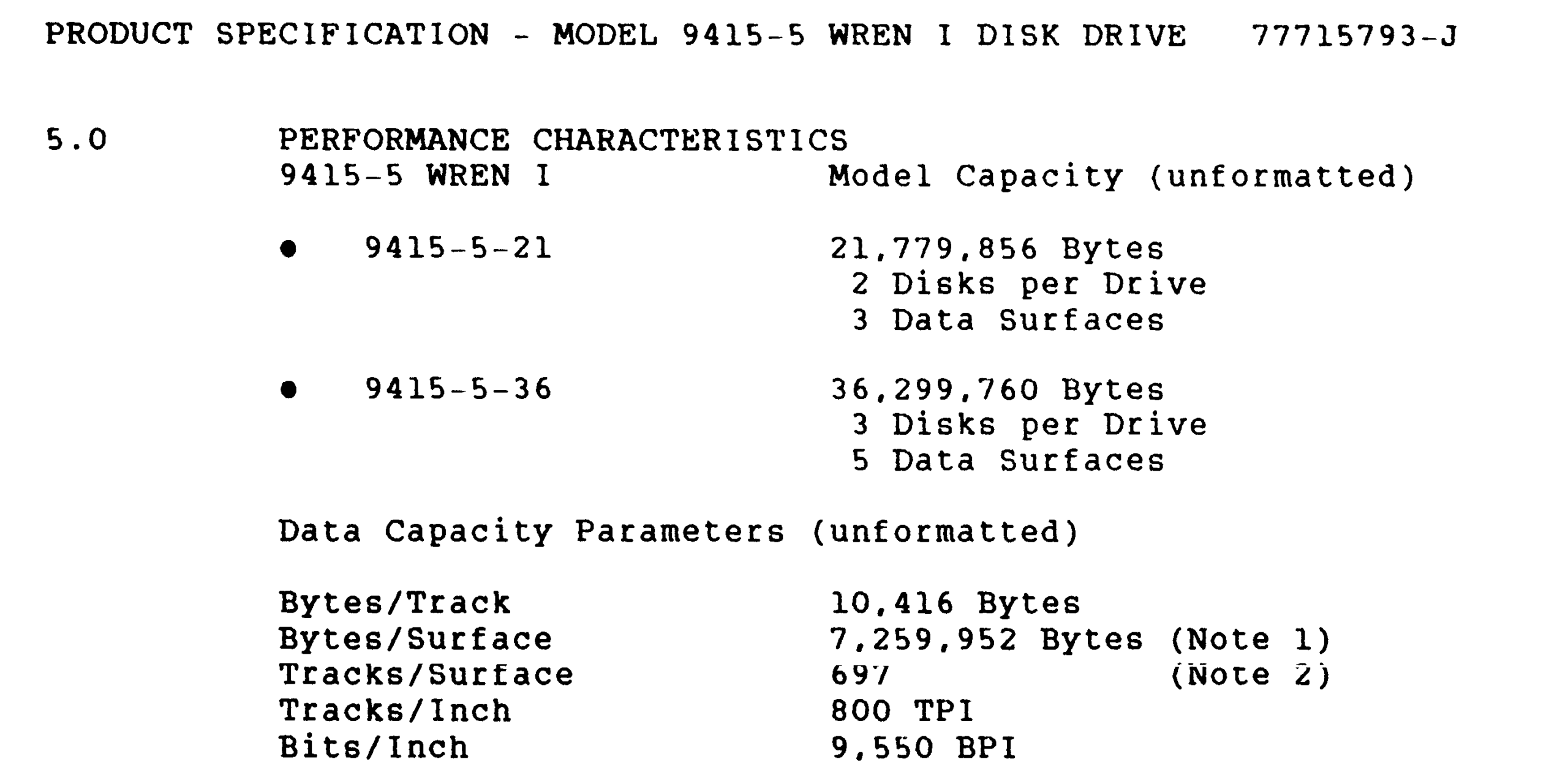
If my understanding is correct then CPMSYS.LIB supports the larger CDC drive. It also supports the smaller Disctron and Rodime alternatives.
CPMSYS.LIB also supports the Adaptec ACB-4000 and the Pulsar P6204 SASI card (as would be expected). The configuration file has been copied to CPMSYS2.LIB which is configured for a Miniscribe 3012, but i do not have the original hard disk so i’ll be starting with a new emulated disk.
There was also provision in CPMSYS.LIB for configuring floppy drives, a Pulsar RAM card, printer buffer, and virtual disk.
The maximum supported logical disk size is 1024 x 8kB blocks ie 8MB but, there is provision for breaking a physical drive into multiple logical drives up to a maximum of 4.
The CDC disk has 697 cylinders, 5 heads, and 32x256B sectors per track which i make to be 27.2MiB or about 28.5MB (so the original number was probably “unformatted”). This can become 4x 6.5MiB logical drives.
CPMSYS2.LIB was edited accordingly. This file is included by the BIOS code, LB34A.MAC. The larger hard disk comes with the penalty of a larger BIOS – presumably related to directory data or buffering. 2k of additional BIOS is set aside if no hard disk is used. With the large CDC drive, 4k is set aside. ie the CPM must be 60k.
Following the instructions in NOTES-32, the BIOS has to be reassembled and linked using the Microsoft Z80 assembler and linker:
M80 =LB34A.MAC
L80 LB34A/N,LB34A/M/X/E
The system also needs a boot ROM (the one that is on the board was ok), and a boot loader for the system track. NOTES-32 says to use the LBHLDR11.MAC as the boot loader for 60k CP/M. The file contents confirm that it is intended for 60k CP/M. Exact instructions for assembly and link are not given but i used the one above as a pattern.
M80 =LBHLDR11.MAC
L80 LBHLDR11/N,LBHLDR11/M/X/E
Then a 60kB CP/M needs to be created.
MOVCPM 60 *
SAVE 60 CPM60
The last thing that is required is a means to write the system track. There is a source file for this: SYSGHARD.MAC. Again following the pattern:
M80 =SYSGHARD.MAC
L80 SYSGHARD/N,SYSGHARD/M/X/E
Then it can all be put together using the 60k hard disk script, HGEN60.SUB which contains:
;use: submit hgen60 <loadername> <biosname>
;inputs: loadername.hex, biosname.hex, cpm60
;xsub.com, zsid.com  must be on default disc
;creates system file SYSGHARD.COM
XSUB
ZSID
ICPM60
R180
I$1.HEX
R880
I$2.HEX
R
ISYSGHARD.HEX
R
G0
SAVE 58 SYSGHARD.COM
This is not quite the same as the script in the NOTES_32 file.
Note that the script requires XSU.COM and ZSID.COM. It produces SYSGHARD.COM.
SUBMIT HGEN60 LBHLDR11 LB34AI had trouble getting the script to execute completely so i just did the steps manually. A mystery.
The instructions end at this point, but the system track still needs to be written. This done by executing SYSGHARD.COM.
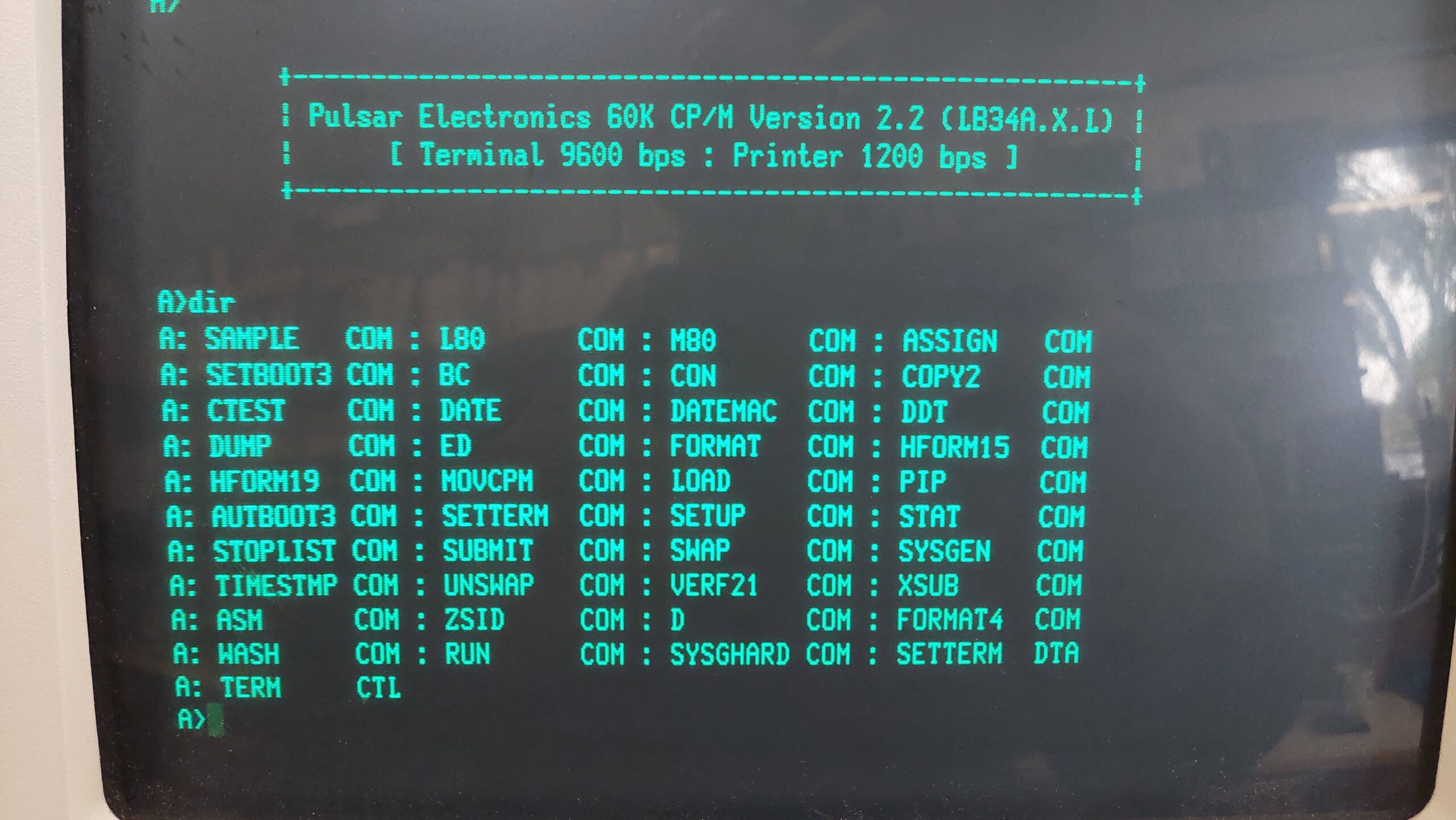
I was stunned and amazed to find that, on reset, the system booted from the hard disk, albeit with another serial communication cocktail: 9600 baud, 7 data bits, 1 stop bit, even parity.
Note that the system needs a floppy disk drive to be connected otherwise it will hang when checking for a boot disk in the floppy drive. If the floppy disk drive contains a bootable disk then it will take priority over the hard disk.
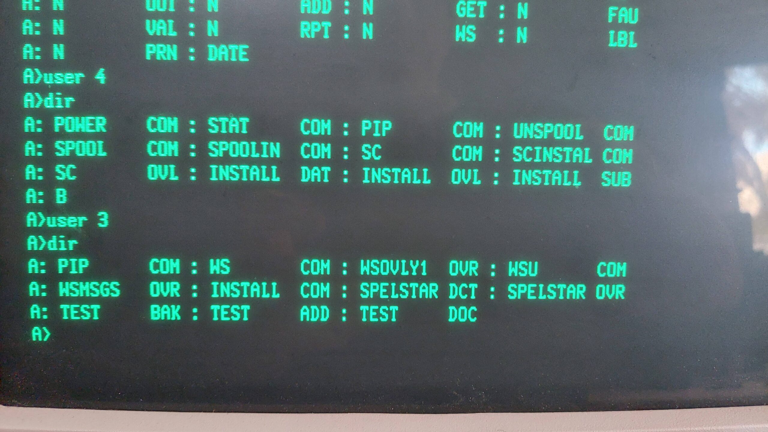
The hard disks are A to D and the floppy drives E and F. A directory listing of A: showed a bit of a mess really. I’ve encountered this before with SCSI2SD and Pulsar. It seems like the format program does not write E5 across the whole disk. In TurboDOS there is an ERASEDIR program that tidies this up but not so with CP/M. Instead, i created an E5 disk image on my PC, wrote it to the SD card using dd, and then rewrote the system track on the machine using SYSGHARD.COM.
CP/M 2.2 supports user areas which can be used to quarantine different work environments. The implementation is not as slick as TurboDOS, which allows the user area to be used in much the same way as a drive letter. TurboDOS also maintains access to area 0 regardless of the current user number. And Turbodos has a copy program that allows files to be easily copied from one zone to another.
Without these features the first trick is to get pip into other user zones:
e> pip
*
e> a:
a> user 1
a> save 28 pip.com
Once it is in the zone the [G<user>] option can be used to pull in files from other zones eg zone 0 on floppy disks.
The hard disks have an 8kB block size, and with typical CP/M files being quite small, this wastes a lot of the available space.
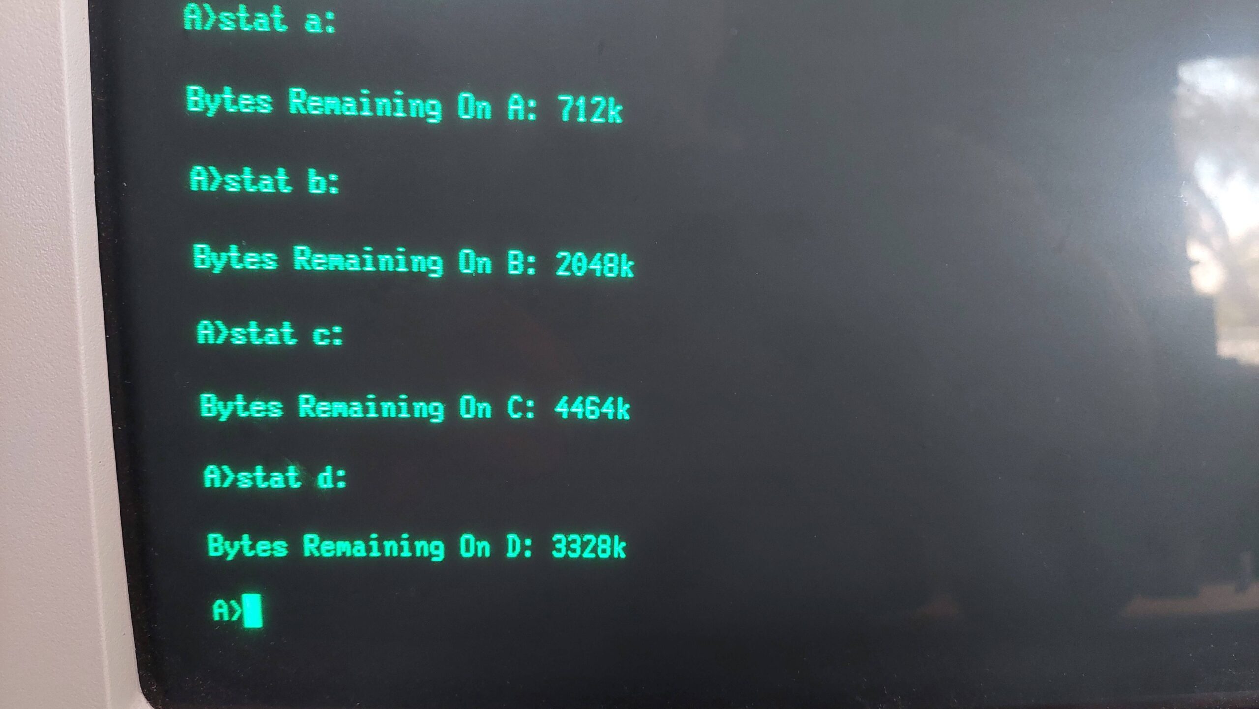
I set up the hard drive as follows:
| User | A | B | C | D |
| Total | 6616k | 6616k | 6584k | 6552k |
| Remaining | 576k | 2048k | 4464k | 4376k |
| 0 | CP/M Utilities (103) | |||
| 1 | CP/M Setup (103) | |||
| 2 | Turbo Pascal (55) | |||
| 3 | Wordstar (21) | |||
| 4 | Supercalc (364) | |||
| 5 | Mbasic (66) | Games (89) | Voice Synthesiser | |
| 6 | MT Pascal (47) | MT Pascal Support Files Development (49) | MT Pascal Gen Purpose Dev (50) | MT Pascal Programs (51) |
| 7 | DBASE II 2.4 (453) | |||
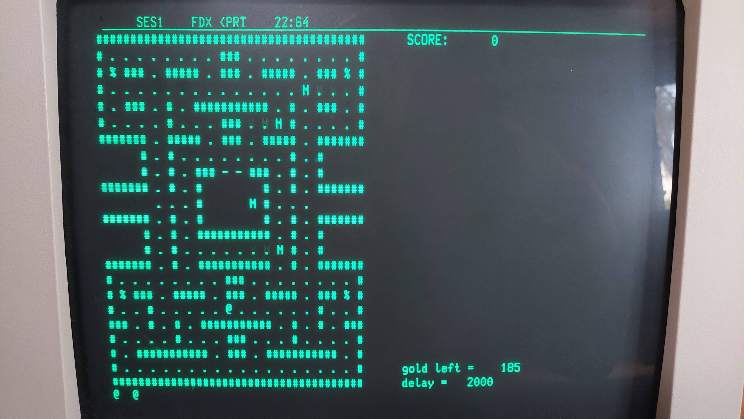
| 8 | Games (71) | |||
| 9 | Fortran (57) | Fortran Sources (393) | ||
| 10 | Cross Assemblers (8) | |||
| 11 | CBasic80 (63) | |||
| 12 | Cobol (64) | PLI (65) | ||
| 13 | ||||
| 14 | ||||
| 15 |
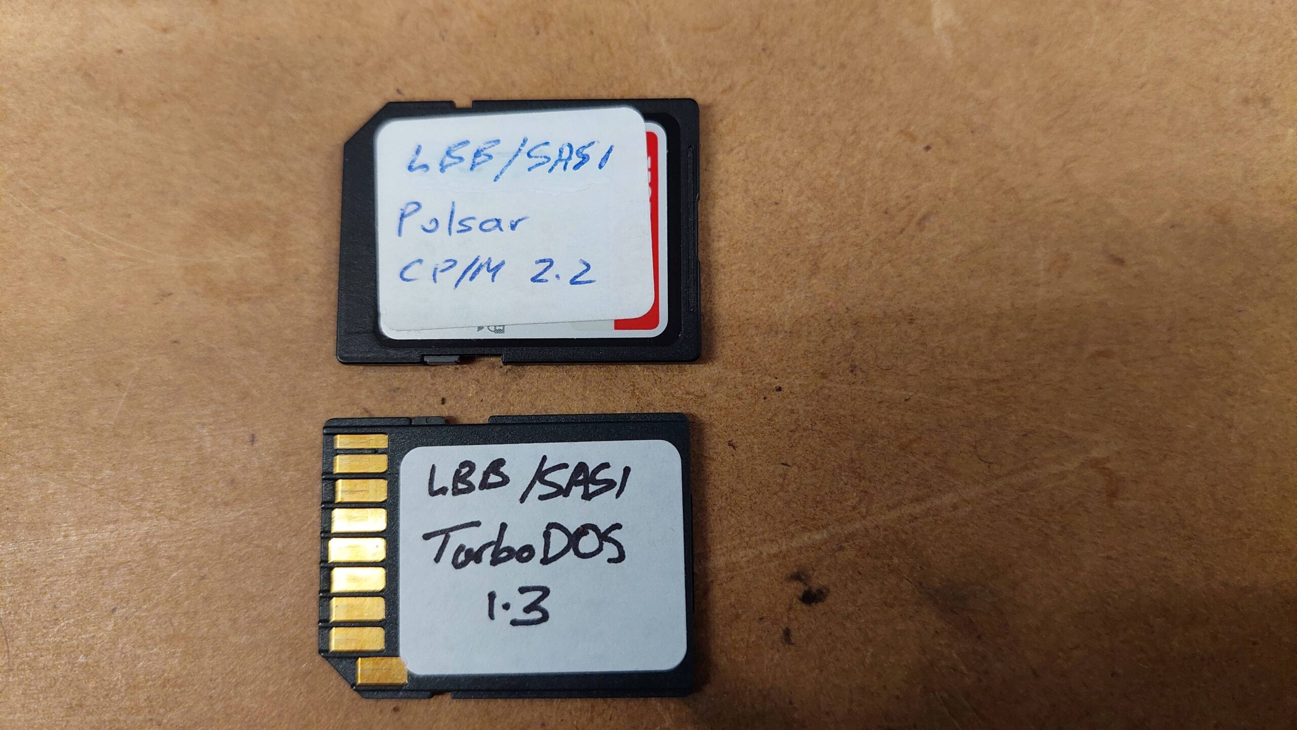
This system is now ready to go. Changing between TurboDOS and CP/M system is as simple as swapping over the SD Cards.
Note that most of the disk images that i have used are available from the Microbee Technology repository, or you can just contact me.