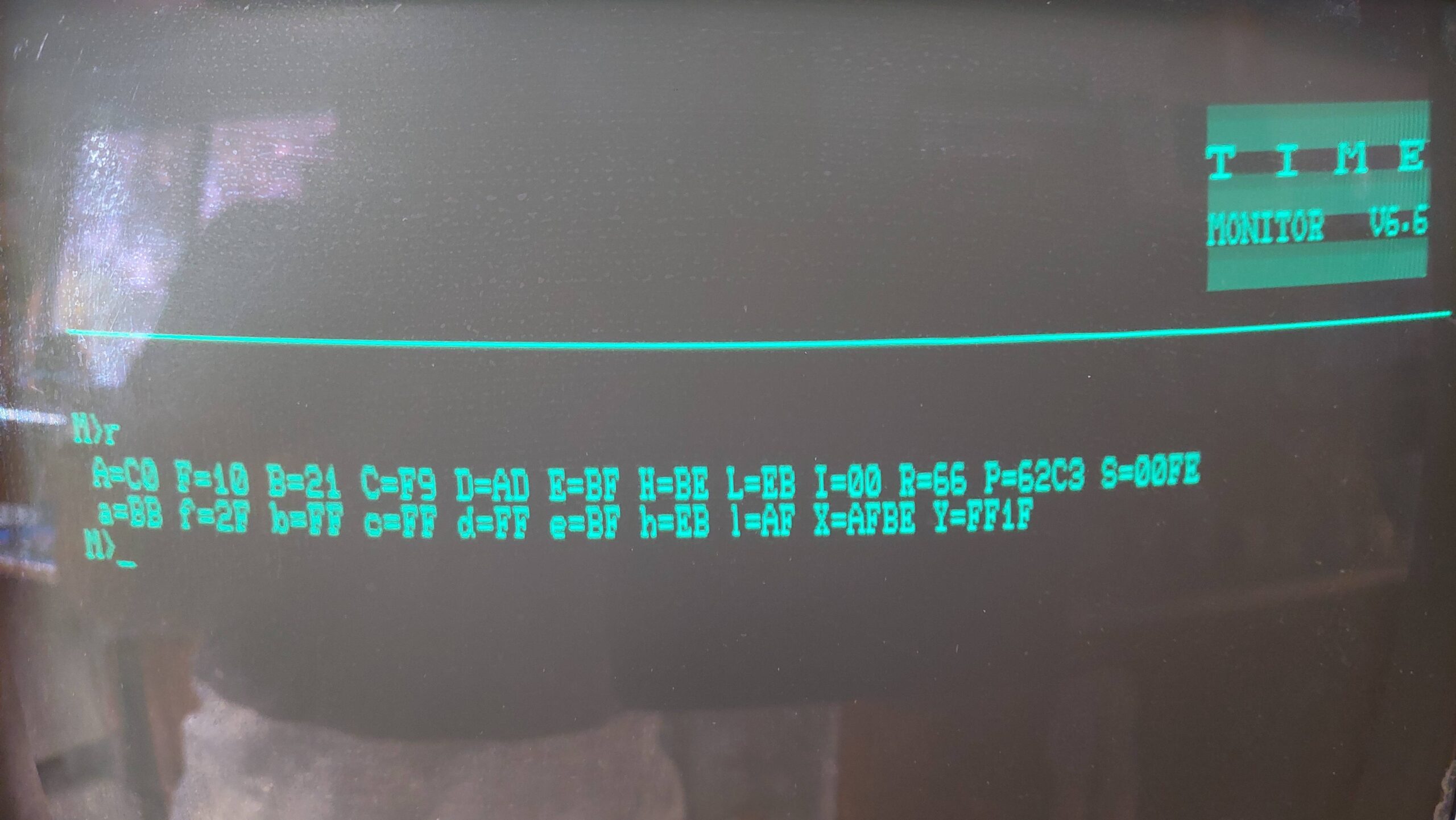
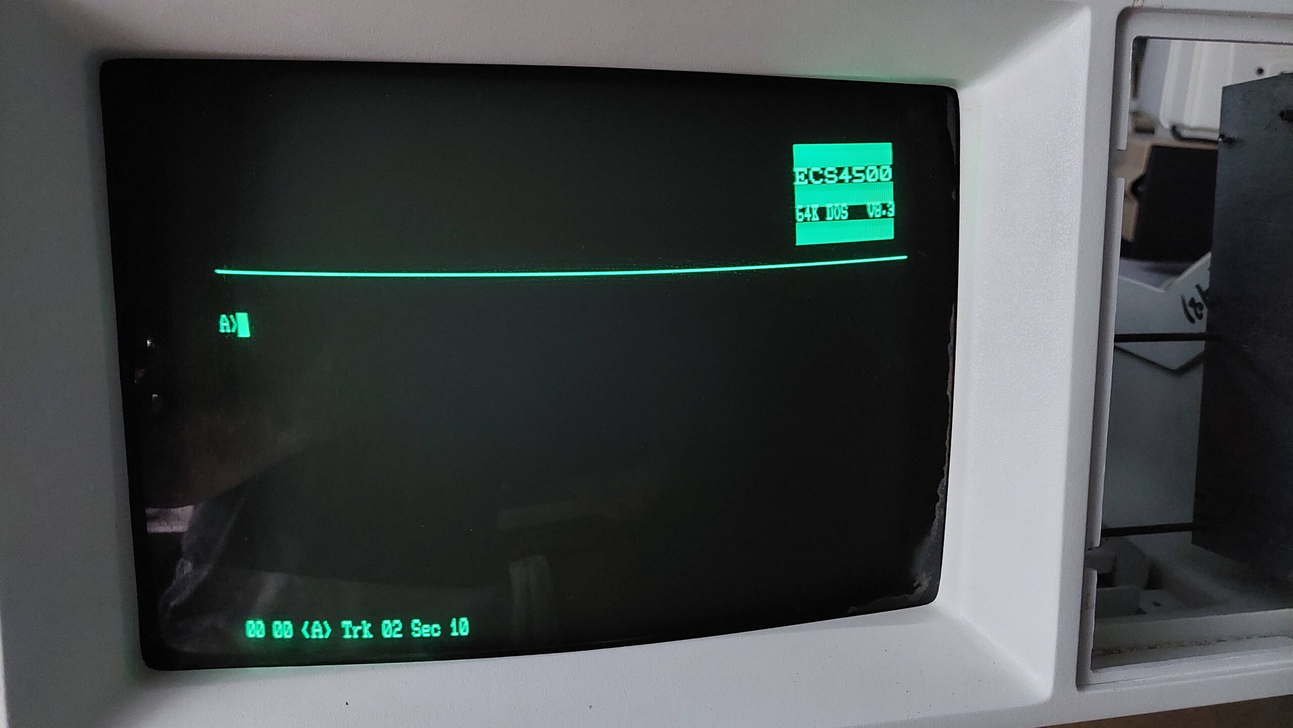
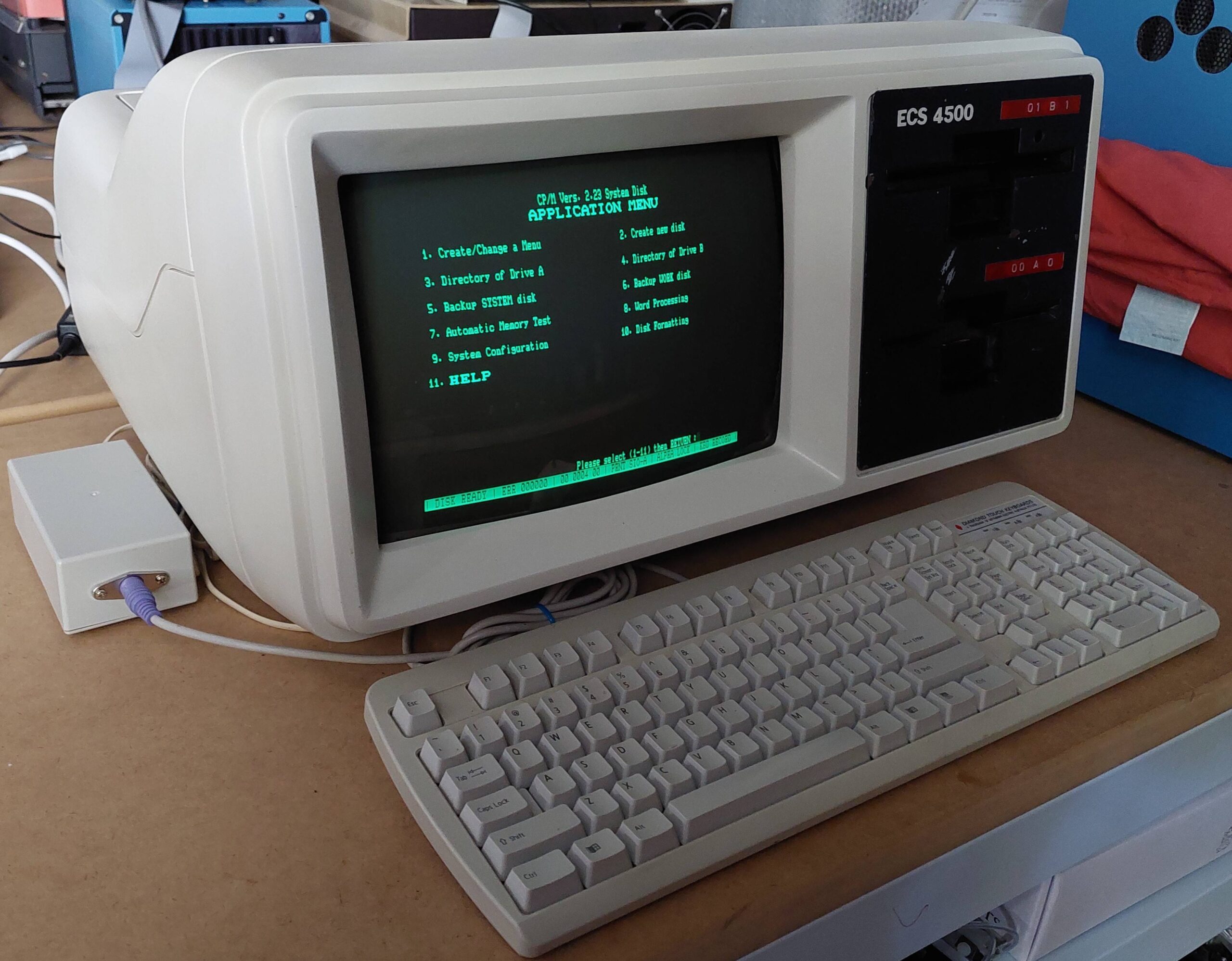
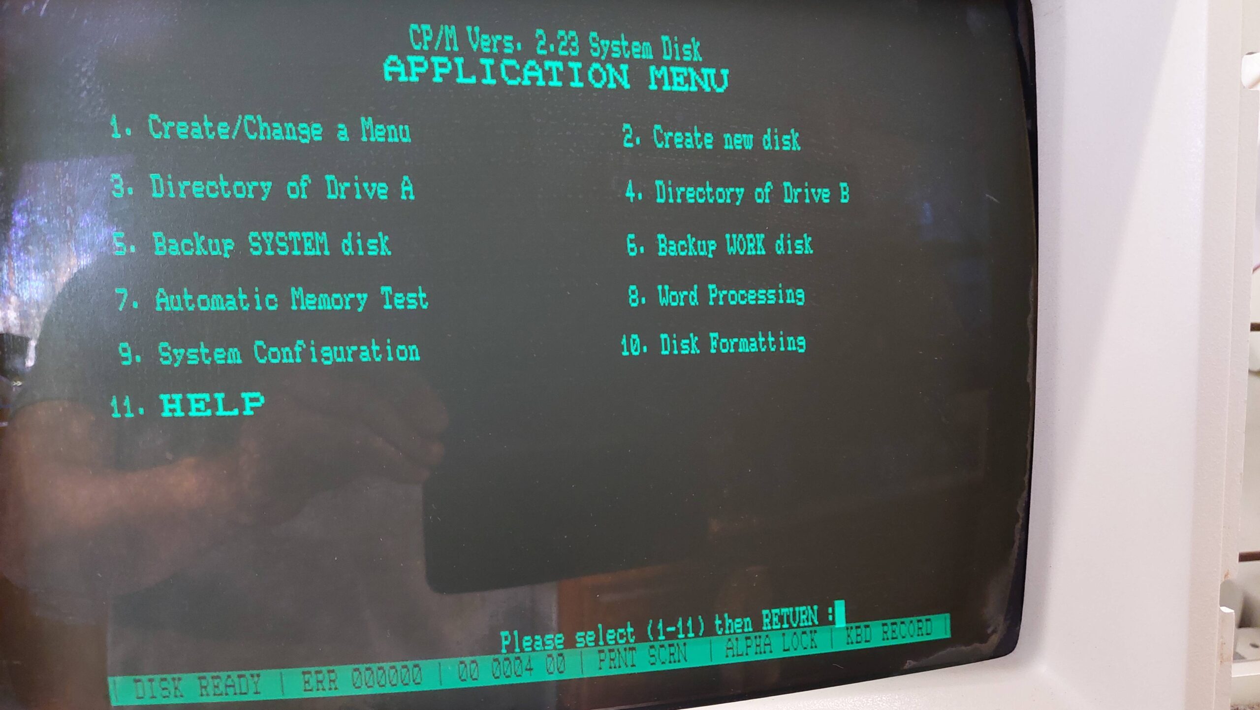
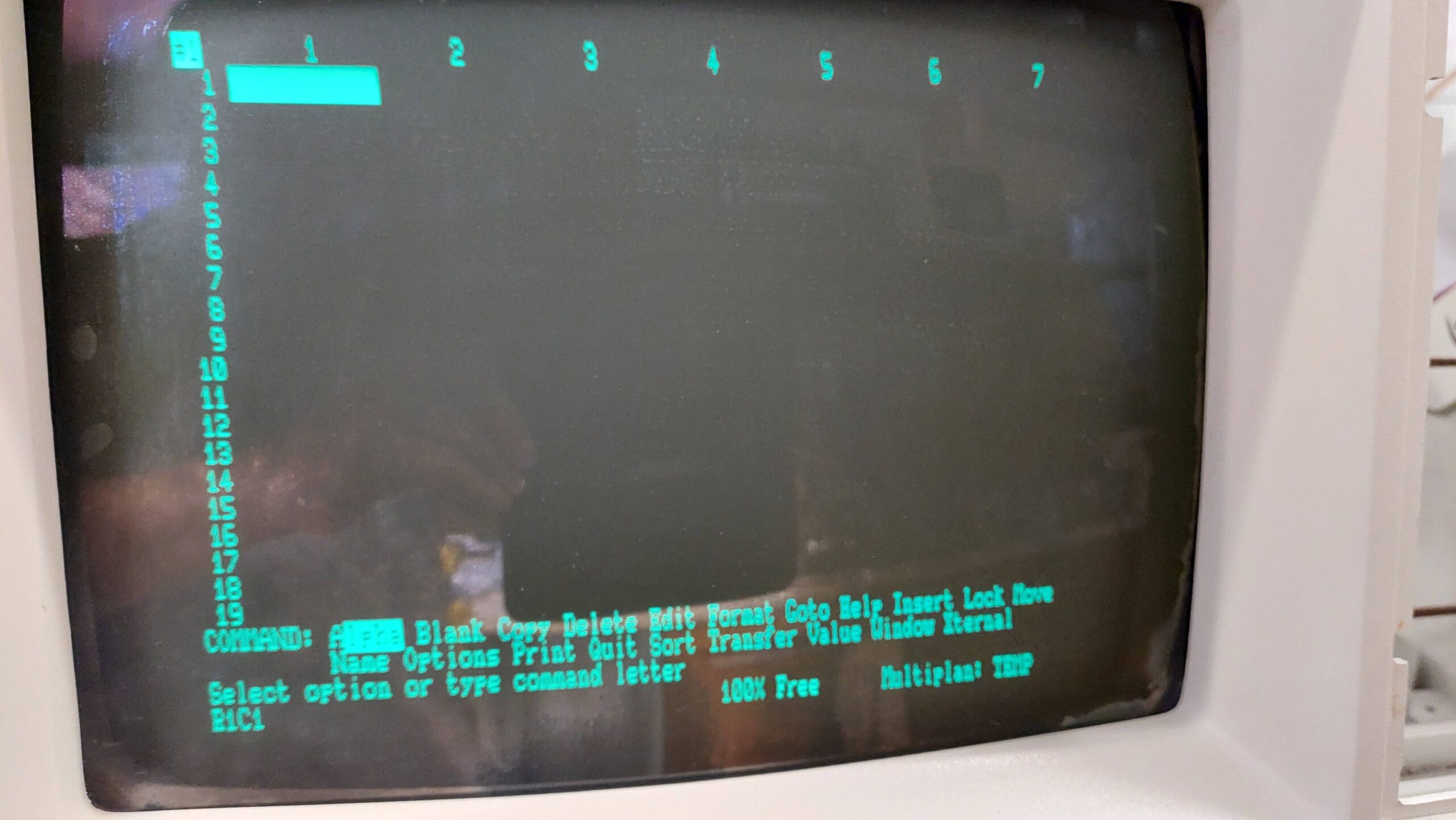
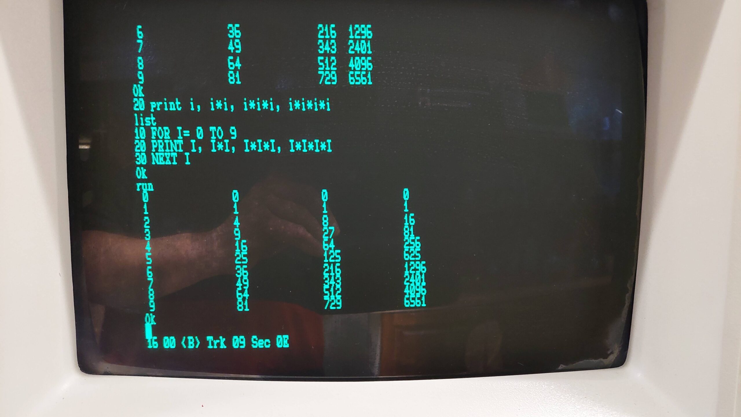
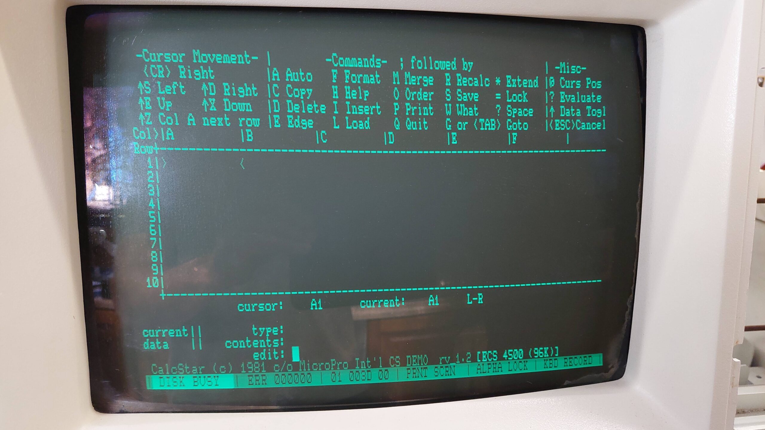
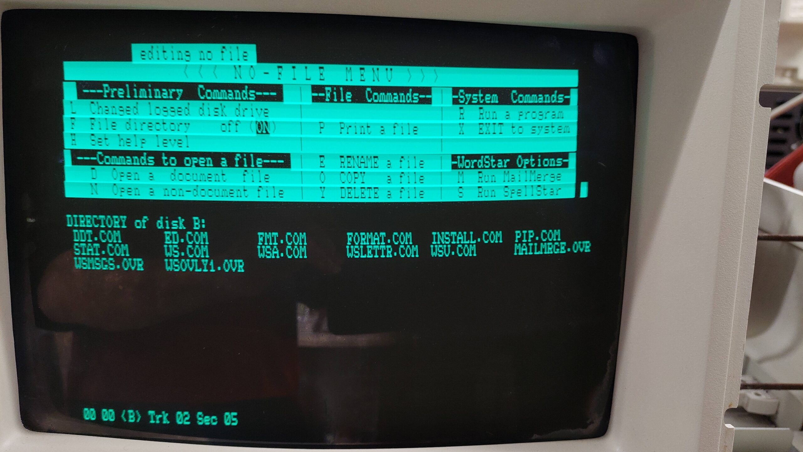
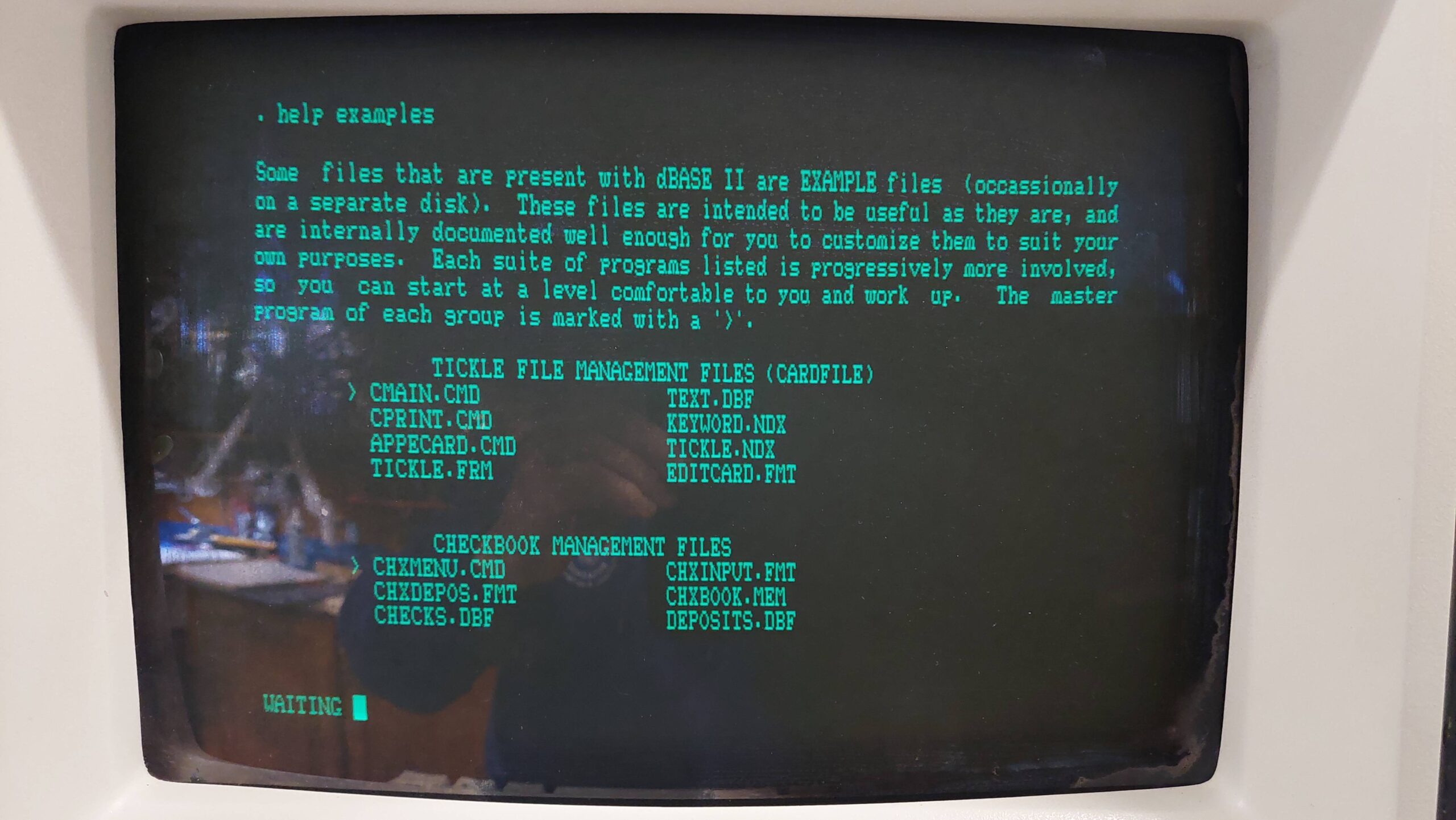
With a semi-operational keyboard, it was possible to use commands in the Monitor (aka “Executive”). Commands are documented in the Time 4550 Operating Manual.
Importantly, it was now possible to issue a Load command.
I had already imaged the disks that came with the machines. I did this two or three years earlier, when Michael first acquired the machines.
I put the disk images on to a Gotek running FlashFloppy. At first there were just errors, but it was good that the machine was even trying to read the emulated disks. The select lights were coming on as expected.
Often it looked like the machine had thought that the code had been loaded and had attempted to run it (the ROM was being switched off) but the screen was full of garbage. I thought it could be a RAM problem.
I was able to initialise a disk using the monitor “v” command. When I read it back with a greaseweazle and looked at the image in the HxC software, it did seem like the initialisation had worked.
I left the gotek attached, and while i was messing with the keyboard mappings, i was surprised to find that it had booted. This only happens with the first image which is the 64k version of the system. Ok, i thought, i’ll run with that for now!
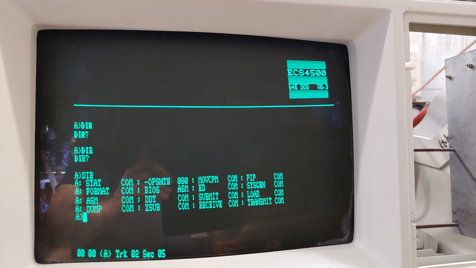
The three DIR entries above were with different scan codes.
I was dismayed to find that the mappings did not seem to work, but in many cases changing to alternative scan codes fixed the problems.
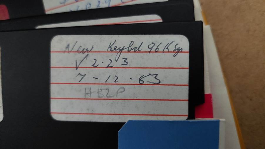
One of the disks does suggest that there was a “new keyboard”. The ROM would allow for different mappings for different keyboards, perhaps.
Still, only one disk image booted. When I looked at the images with the HxC software they seemed to have the wrong number of tracks. I did these images a couple of years ago using one of the drives in this machine, but it didn’t seem entirely reliable then. Since then, I have acquired several of the same 77 track 100TPI drives (although this machine seems to push that to 80).
I re-imaged several disks using the single Micropolis drive unit from the Exidy Sorcerer, and this returned much better results with the gotek.
A couple of the system disks complained that the “floppy disk gate was not closed”. I thought this must have been a door closed signal that’s being expected. What it was trying to say is that the controller expects Ready on pin 6 because that is where it is on Micropolis drives. On a gotek it is on pin 34 and pin 6 is unused. I added a wire on the controller to connect pin 34 to pin 6.
Warning: This description is lengthy and technical. The punch line (TLDR) is that ECS runs the drives at about 285rpm rather than 300rpm and that messes with a lot of tools.
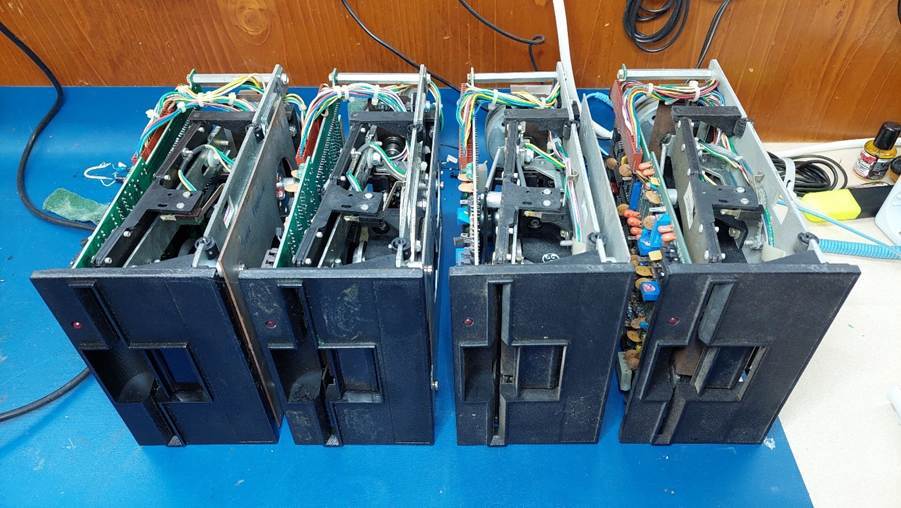
I had previously done some work on the two drives in this unit but neither of them was good. One had a dud tacho in the spindle motor. I had previously used the other to copy some of the disks, but I was not sure how well it was working.
The other two were very dirty:
Blew out the leaves, webs, dust
Cleaned out the grease on the door lock and head shaft and re-greased.
Cleaned heads
Replaced missing felt in top “head”.
I put both viable drives on ImageDisk and formatted a disk on each and then ran an alignment test. All good. Then I swapped the disks and not all was good. There was a discrepancy on tracks 76 to 77. This resolved with cleaning the lead screw.
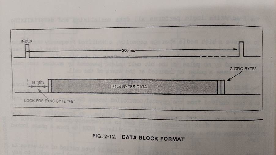
The format is interesting; 80 tracks on a 77 track device for a start. There are no physical sectors – just tracks with each track having a CRC. According to the technical manual each track has 6144bytes of data with two bytes of preamble and a single byte sync. The checksum is 2 bytes. The total count is 6149 bytes. This means that if one bit is out the whole track is dead. There are 48 logical sectors.
That gives 491k on a single sided disk cf 180k on an IBM single sided disk or 6.144k per track compared to 4.6k for IBM. That’s 4:3. How? There is no sector overhead and the whole track is used – very tightly. At 250k/s this data would take 197ms to write. One rotation at 300rpm takes 200ms so this is tight.
According to the Micropolis manuals, the drives spin at 300±6rpm. The period can be as small as 196ms. The normal bit rate for double density 5.25” drives is 250k/s. That’s 49kbit/track or 6.127kB/track. That means that there would not be enough space for the ECS track data.
I imaged all the disks using the Sorcerer single drive unit and greaseweazle v4. It was a struggle to gets disks to operate reliably with the sorcerer and I can’t be 100% confident that the single drive unit is perfectly aligned. It has been working fine for reading and making sorcerer disks though. The Sorcerer drive runs very close to 300rpm.
Looking at the fluxes with the HxC software, it appears that the bit rate is a little higher than the “standard” 250kb/s. Instead of seeing intervals of 4, 6, and 8us (as expected for 250k MFM coded data), there intervals are 3.8, 5.6, and 7.4. This is reading “factory” disks at about 300rpm. This is about 265kbit/s. That’s 52kb/track or 6.49kB/track which is sufficient to hold the documented track data.
Nominal 4us
Nominal 6us
Nominal 8us
Disk 10 (299rpm)
3.8
5.6
7.4
Disk 11 (299rpm)
3.8
5.6
7.2
Disk12 (298rpm)
3.9
5.5
7.4
So the data rate for the ECS system is higher than the norm or, noting that both of the drives seemed to be running quite slowly, it is also possible that the data rate is normal but rotational speed is lower.
Regardless, I would expect that reading and writing with the same drive would preserve the data rate ie the archive drive speed should not matter.
I tried some experiments:
Sorcerer drive =300rpm
ECS Drive = 277rpm
In principle, it is possible to write SCP images back to disk, but in practice the errors pile up. It’s usually better to convert to HFE and then back to SCP which has the effect of “tidying things up”. HFEs can also be used in a gotek.
The HxC software may handle the strange timing well – or it may not. It’s hard to say. It certainly gets confused about rotational speed when using the track analyser. It looks like to tries to change RPM to correct the data rate.
a. Read disk 31 using sorcerer drive to SCP. b. Convert to HFE. This averages the timings – 7.75us. c. Write HFE to sorcerer drive. This writes clean timings to disk. d. Read back using sorcerer drive. e. Convert to HFE. f. Surprise result: The data rate has increased again. I smell a rat; 7.75us is now 7.5us.
a. Read disk 31 using sorcerer drive to SCP. b. Write SCP to sorcerer drive. c. Read back using sorcerer drive. d. Convert to HFE. Same result: The data rate has increased again. 7.75us is now 7.5us. This cuts HxC out of the loop. This is a greaseweazle thing!
a. Read disk 31 using sorcerer drive to SCP. b. Convert to HFE. c. Write HFE to ECS drive. d. Read back using ECS drive. e. Convert to HFE. Another surprise result: The data rate has slowed down. 7.75us is now 8.0us. The drive is running slow: 277rpm.
a. Read disk 31 using sorcerer drive to SCP. b. Convert to HFE. c. Write HFE to Sorcerer drive. d. Read back using ECS drive. e. Convert to HFE. f. Another surprise result: The data rate has slowed down. 7.75us is now 8.1us. The drive is running slow 277rpm, whereas the sorcerer was very close to 300rpm.
I had expected that the data rate would be preserved if I wrote to and read from the same drive. It was not. I still can’t work out exactly what is going on here, but I suspect that greaseweazle is correcting the data rate to 250kb/s when it writes.
It eventually dawned on me that I could observe the data rates on the real machine and I could also have it write to a floppy disk. This quickly confirmed that the data rate is 250kb/s so the drives were definitely intentionally set up to run slowly.
I suspect (pure speculation!) that the original design forgot to allow for inaccuracy in the rotational speed (it is not clear whether the time during the index pulse is useable). Using nominal timing, the available period is 200ms. At 250kb/s this is 50000 bits or 6250 bytes. Recall that 6149bytes need to be written, giving only 100 bytes or 3ms margin.
Perhaps variation in rotational speed or in the index pulse timing caused issues in practice, and the remedy was to drop the rotational speed by 5%. This does have the effect of increasing the bit density on the media by 5% and, given that 80 tracks are used rather than the specified 77 this makes the bit density on the inner tracks much higher than other computers. Track 68 on this machine has the same bit density as track 77 on others eg the sorcerer. This could be expected to make the inner tracks less reliable than other computers.
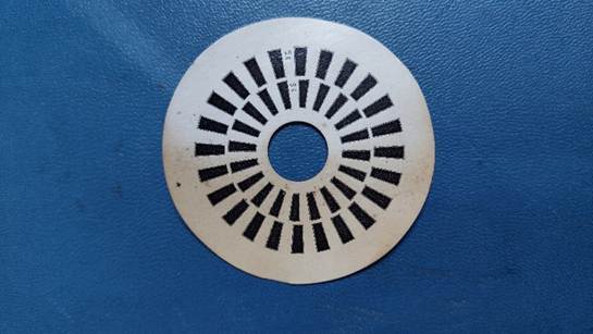
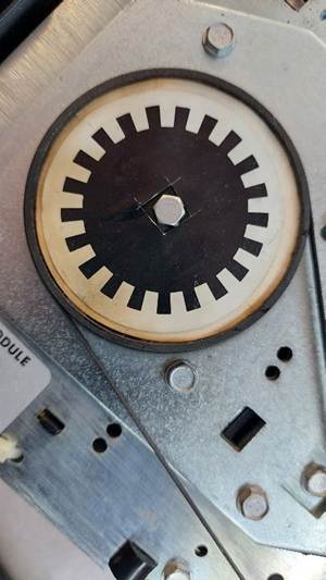
It turns out that ECS printed up new strobe labels with 21 ticks instead of 20 and stuck them on the drive band wheel so that the drives could be easily adjusted to about 285rpm. This combined with the use of 3 tracks above spec probably means that the specified bit density is very high on the inner tracks.
If I write the disk back using the sorcerer drive and then use the disk in one of the slow ECS drives, then the data rate will be lower than the original. This is odd indeed.
If I write the disk back using a slow ECS drive and then use the same drive, the data rate will be correct. Also odd, but perhaps convenient.
Unfortunately, the data rate produced by the Goteks (with FlashFloppy) using the HFE created with the sorcerer drives is incorrect. The cleanliness of this data seems to allow them to generally operate anyway, but they are less than ideal.
The disks have been re-imaged using 285rpm. These images can be written back at 285rpm and all is sweet. The HxC software struggles with the low disk speed. Sometimes it works, sometimes it crashes, but mostly it just processes the data incorrectly so it is no good for HFE conversion. The bit streams are fine though, so maybe one day it will be good. I created HFEs using greaseweazle, and they work fine in the goteks – generally better than the 300rpm versions.
3 of the drives appear to be working ok. The last one has a tacho fault in the spindle motor. It can be a spares unit. One unit had a cracked power connector solder joint. That is probably a result of the constant connecting and disconnecting.
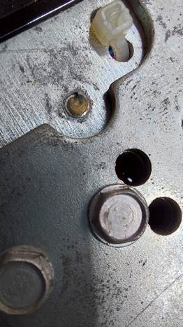
One had a screw broken off (holding the base cover). I drilled it out. It wasn’t pretty. I ended up redrilling and tapping the holes for 4mm screws (some of the originals were missing anyway. I think the covers and screws (and possibly taps) were an ECS thing anyway.
Alignment is tricky. The usual goto is Imagedisk, but it doesn’t recognise the ECS formatted disk. I have chosen a gold standard drive – one that seems to work well with existing disks – and have used it to write an “alignment disk”. This disk has been formatted in imagedisk. I only had to adjust one drive.
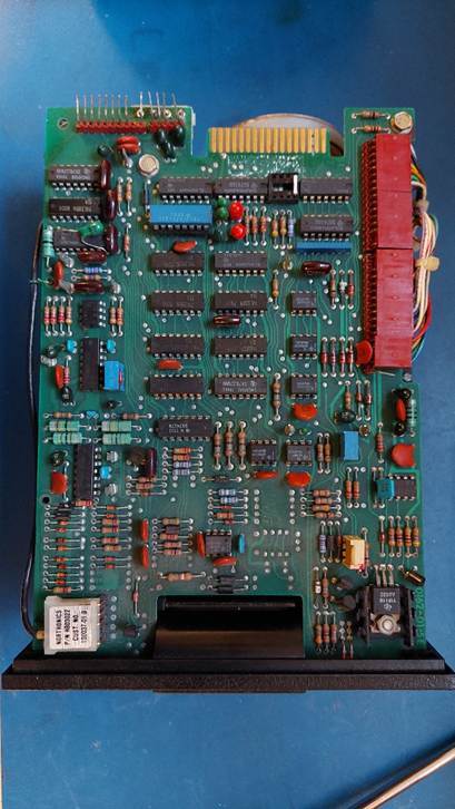
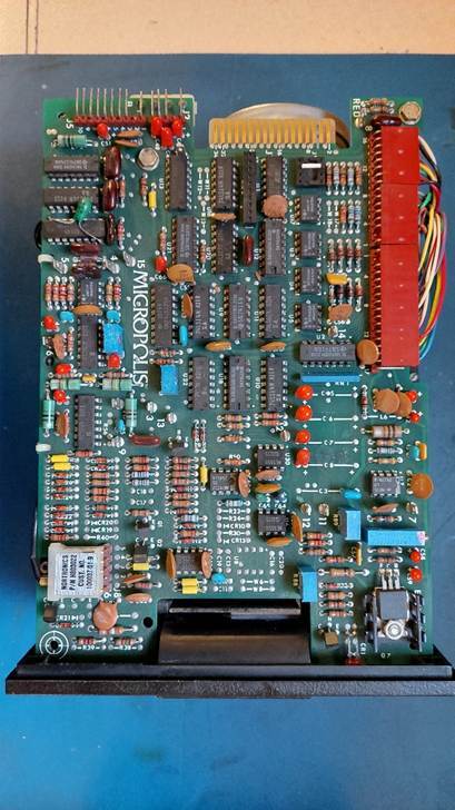
Note that one of the drives is a later version that is not covered by the schematics in the maintenance manual.
The images have been sent to Alan Laughton to add to the Microbee Technologies File Repository. Because the disk format has not been deciphered, the files have not been extracted.
Virginal system disks seem to be absent so it is necessary to construct a couple based on my best guess of what was on them.
There seem to be two main categories of operating system: 64k and FAST. There are different versions of both. The FAST (File Access Storage & Transfer) uses the addition 32k above 64k to improve performance, eg by providing disk buffering.
The Checklist in the documentation is quite specific about the FAST files, so a disk has been prepared based on that list. RUN.COM could not be found.
The 64k version described in the manuals is version 8.3, but the coverage is not comprehensive. The constructed system disk is my best guess based on what is usually on a CP/M 2.2 disk. There are three different formatting programs.
Fresh disk images were created using a pair of goteks. This was mainly done for the FAST 2.22 operating system. A clean OS disk was created and the used as seed for various other disks including basic, wordstar, dbase etc. This was done using a pair of goteks running flashfloppy.
The new disks worked fine both as images and when written to floppy media, but it was not clear what speed flashfloppy would use for writing disks. Looking at the images in the HxC software it seemed that it was writing at 281rpm sometimes.
Just to be completely safe the images were written to floppy media on the machine and then re-imaged at 285rpm. These disks are numbered starting at 101.
It took some time to resolve the ambiguities in the scan code mapping, but that seems to be working well now.
The adapter has been moved into a small box and the PS/2 keyboard added. The PS/2 library did not handle control characters which made things a bit kludgy (as per the Lingo keyboard emulator) with key sequences having to be used.
To resolve this, the library was modified to work with control keys. Mappings were also adjusted to support function and arrow keys.
The original Arduino Uno was replaced with a new unit. A track has been cut to disconnect the 5V from the USB connector. This is so there is no conflict powering the adapter from the ECS 4500. A 1A resettable fuse has been added on the 5V line from the ECS 4500. The protected power is routed to the Uno and the PS/2 keyboard.
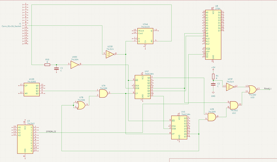
Lastly, the reset circuit was reverse-engineered and the keyboard adapter code modified to allow a reset to be generated by typing Ctrl-R Ctrl-E Ctrl-S.
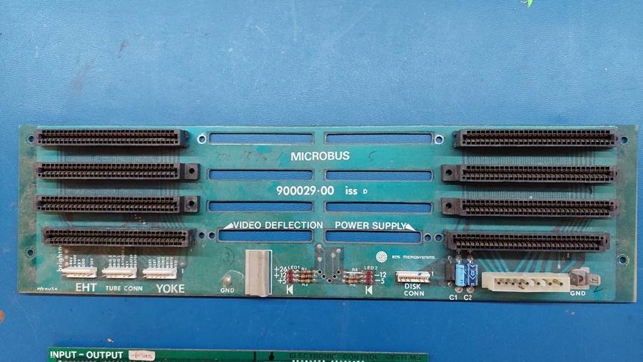
The Input Output board that was originally in the unit did not have PIO so it has been replaced with the spare card. This may allow the use of a parallel port printer.
Ports from left to right looking from the rear:
25 Pin Female D
Daisy Chain Serial Port on RS232 Buffer board. Do not use.
25 Pin Male D
Serial Port on RS232 Buffer Board. This sis connected to the 8251 on the Microcomputer Board. This port is the terminal connection for dumb terminal built into the monitor ROM and initiated with “t” at the monitor prompt. 9600, 8 bits, no parity. A null modem was required to connect to a PC.
25 Pin Female D
Serial Port on Datacon board. This board is connected to the SIO on the Input Output Board. Level shifting is done on the Input Output Board. 2400, 7 bits, odd parity. May be configured as the printer port.
25 Pin Female D
Parallel Port on Intercon Board. This is different from the original configuration which used a Concat Board. The Intercon Board is connected to PIO Port A on the Input Output Board. This may work with a parallel printer but without success so far.
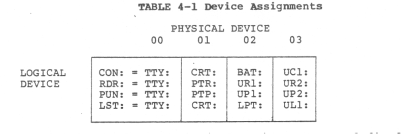
System configuration is important to make these devices work.
The DIP switches on the I/O Board may have an effect. There is some info in the manuals, but it is patchy.
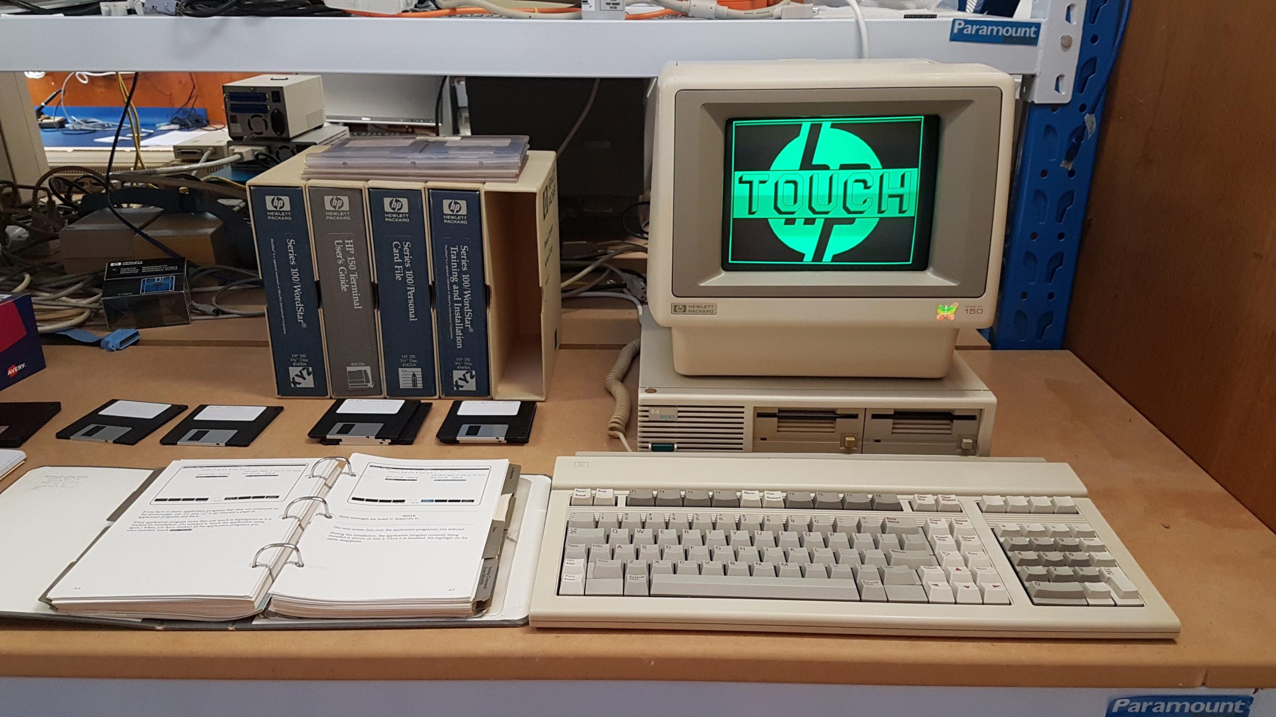
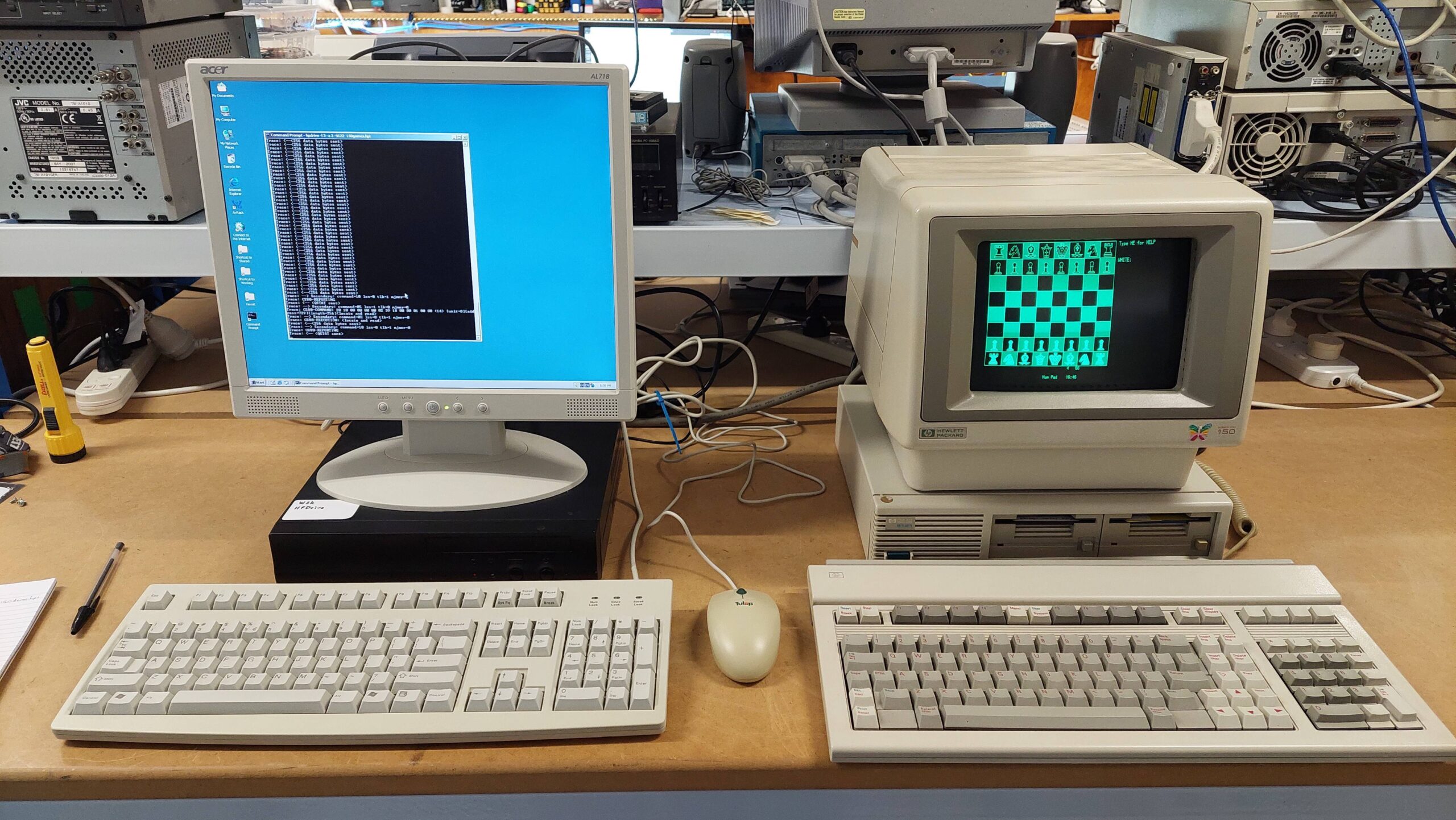
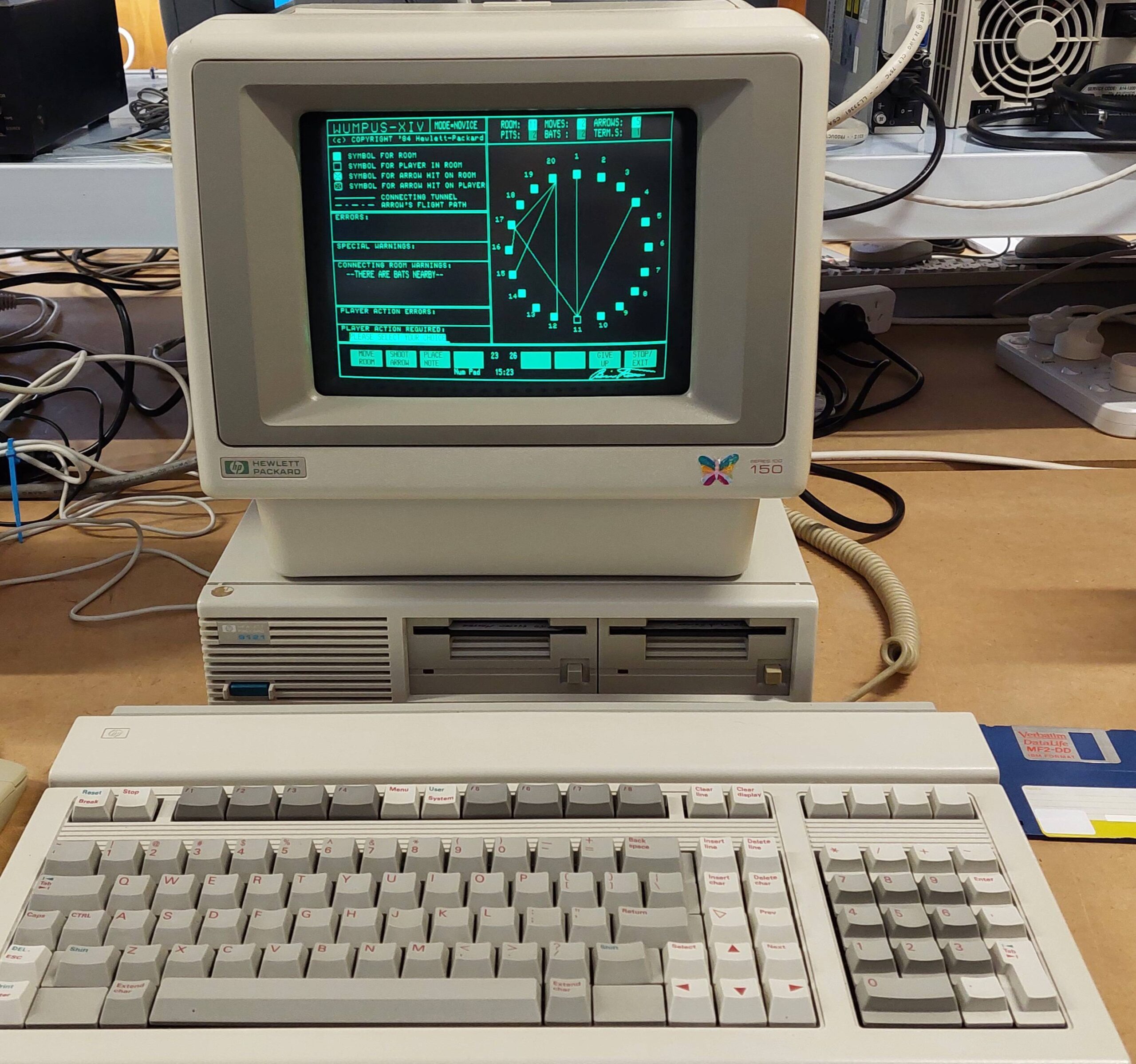
The HP 150 is a remarkable machine that never fails to impress, even though commercially it did not do well. The computer itself includes the very sharp green monitor and makes provision for a printer as well.
It runs MS-DOS 2, but it is not an IBM compatible machine.
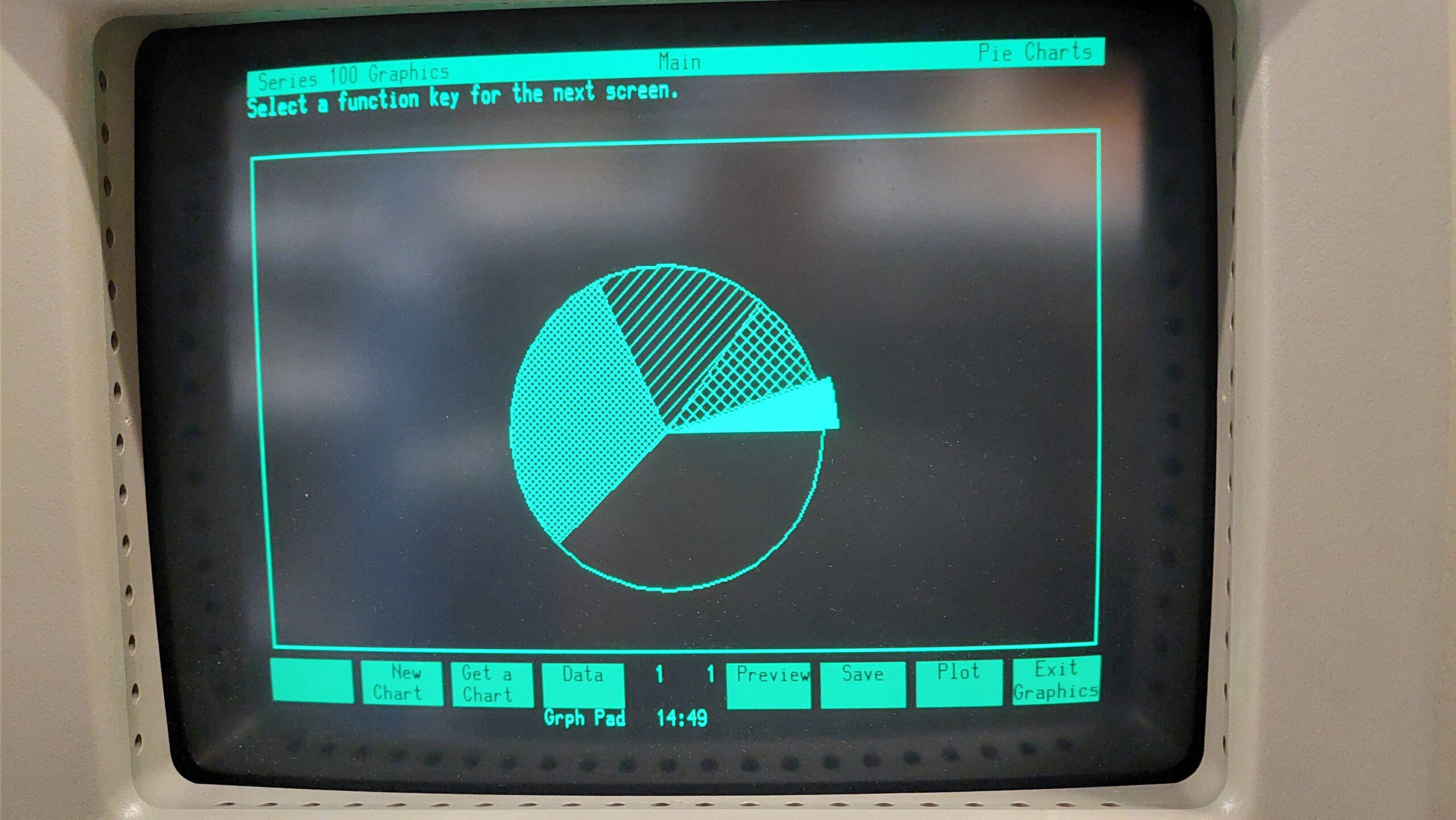
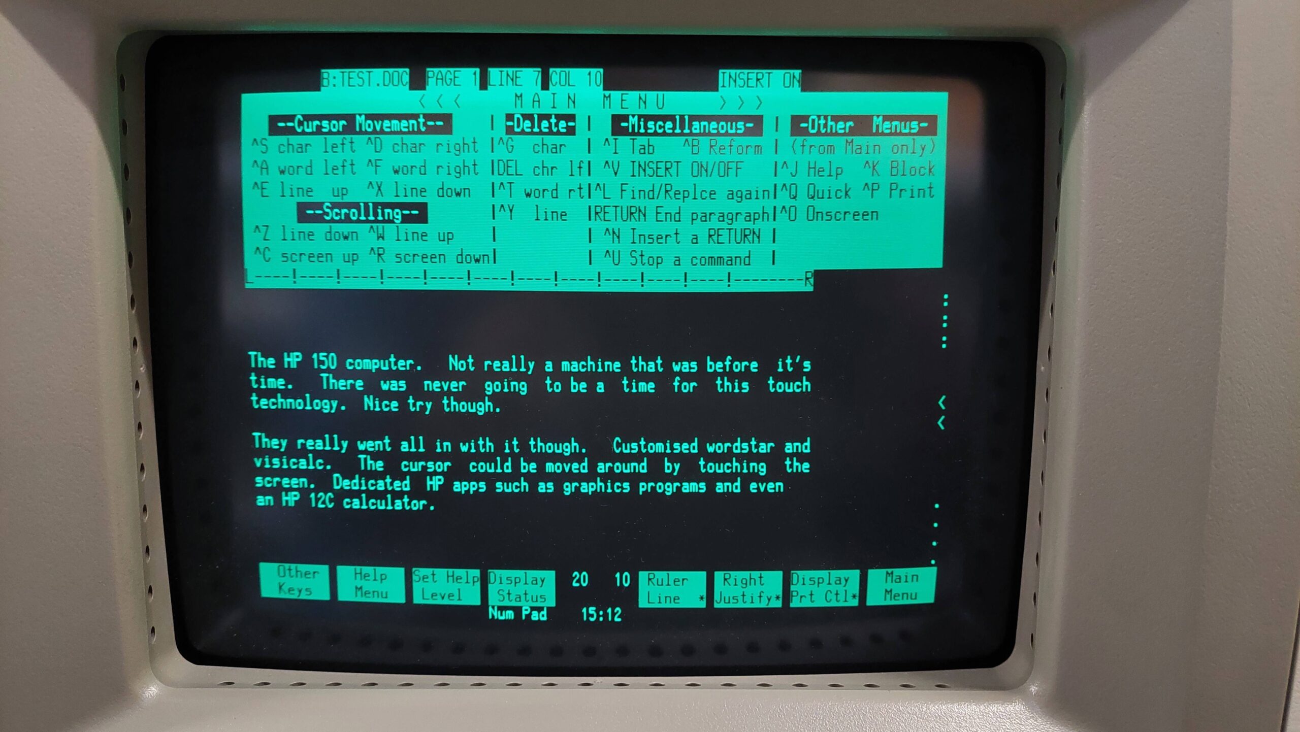
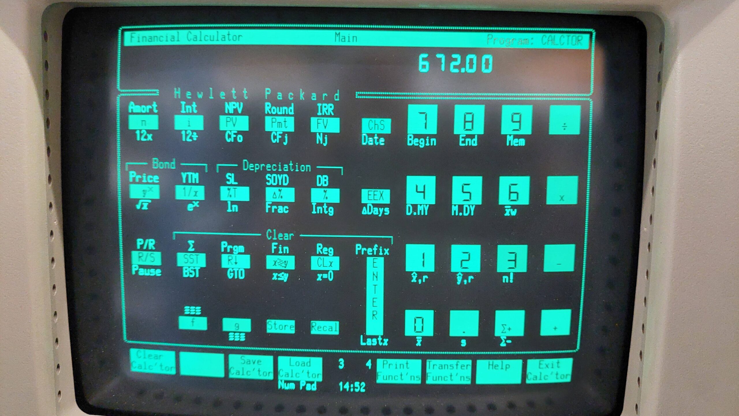
The most surprising features are the touch screen and program enhancements that use it. This was a significant investment by HP.
This machine was a FB marketplace purchase all the way from Bundaberg. The seller was the original owner. He purchased it back in the early eighties to support his surveying business. He said that he wanted a quality machine, and that meant HP.
If you look carefully, there’s a child’s sticker near the 150 at the bottom right of the monitor. Perhaps from a now adult child. I’ve left it there.
I knew it had a video RAM fault when i bought it and that took a little work to resolve. The disk drives are Sony single sided 3.5″ units – a very early adoption of this technology – that needed a good clean to operate. Apart from those issues, this machine was good to go.
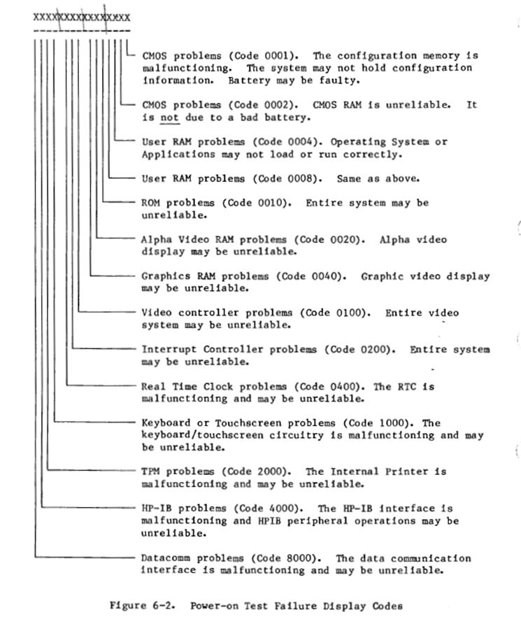
This machine had been powered up recently, so a felt ok about switching it on. The power on self test had given an error code: 1040. I had grabbed the service manual and looked up this code before i purchased.
The Service Manual has info on interpreting the code and on the LED readout visible through the back panel.
1000 means keyboard or touchscreen problems.
0040 means a graphics RAM problem.
It took a couple of power cycles to get the error codes from the LEDs at the back of the unit. Each error has four nibbles that are shown one at a time.
The LEDs gave the following:
EC40: GRAM Travelling test failed
E840: GRAM Marching test failed
9120: Keyboard did not identify as being present.
Clearly, there were two quite separate problems. There were no batteries, so I expected 0001 error – but didn’t get it.
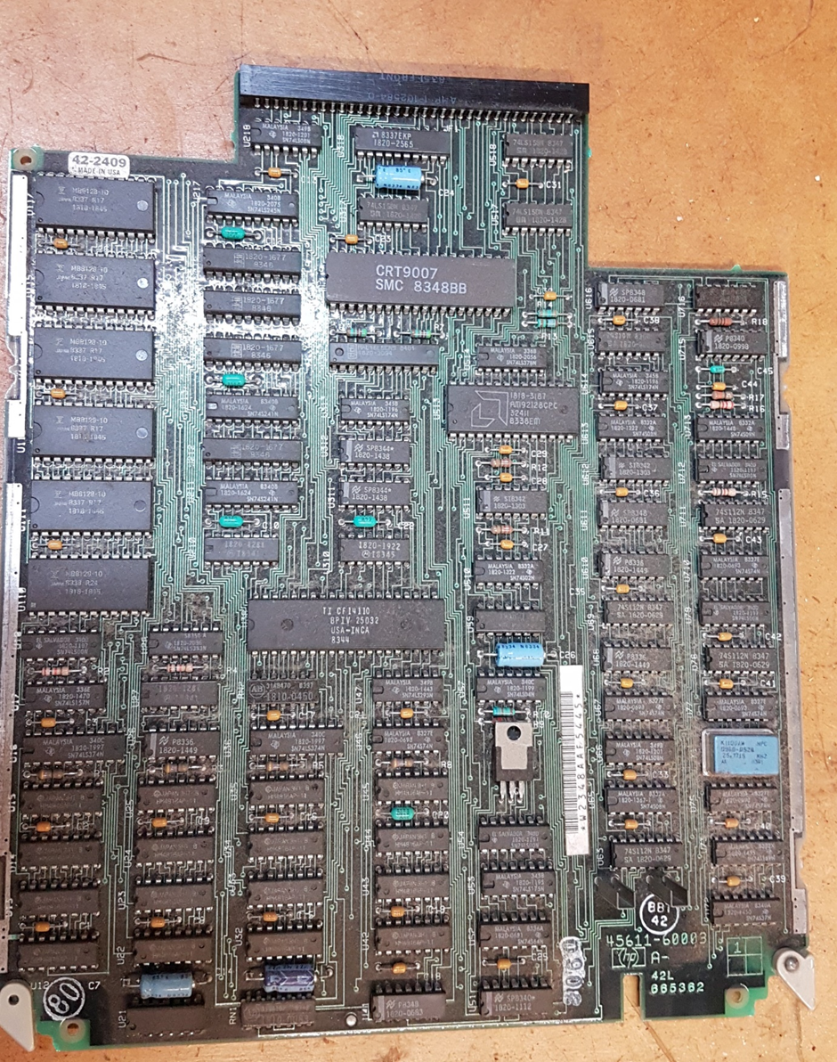
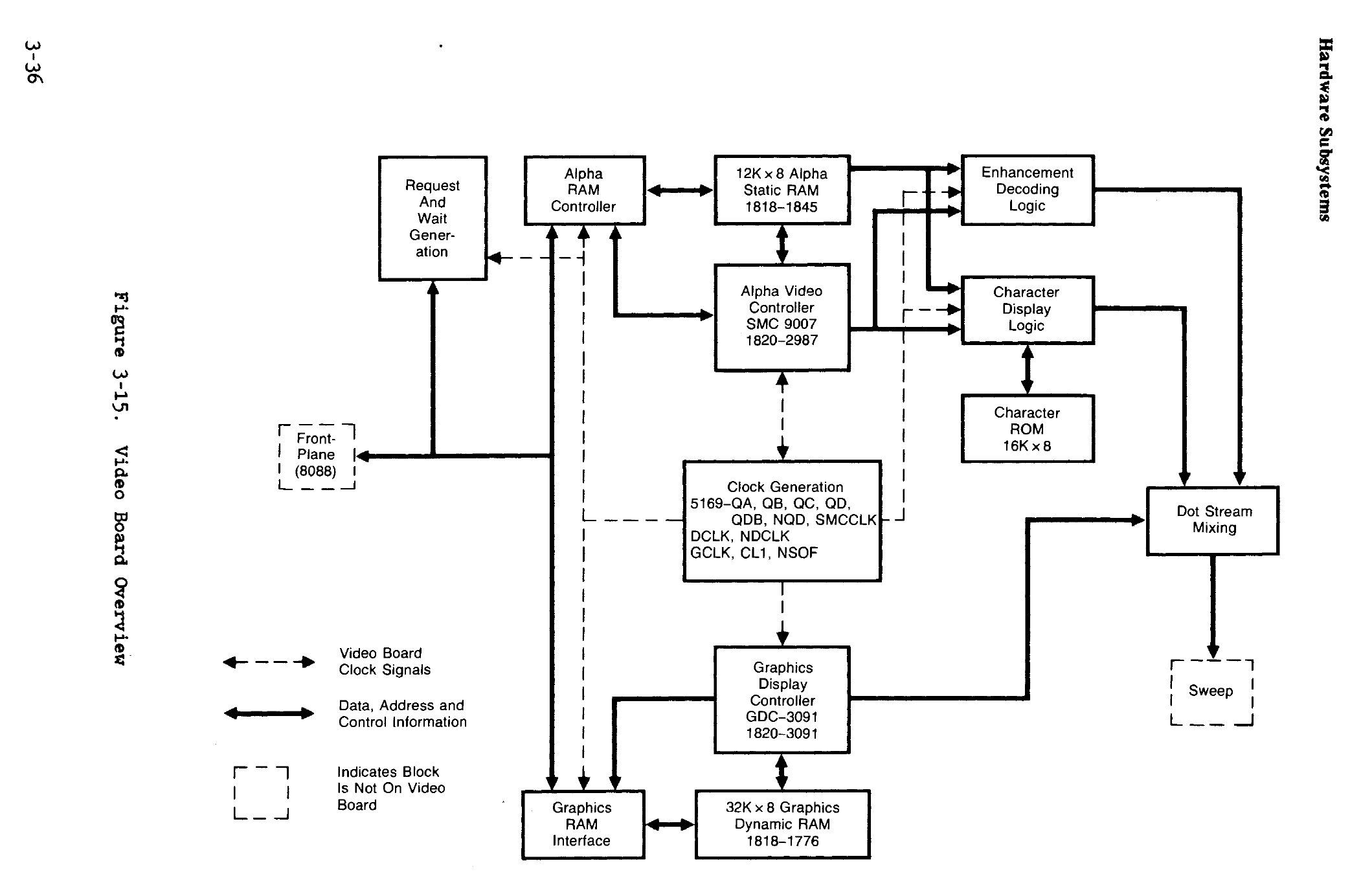
The Graphics RAM tests look like they have 512 slots. It has 512 horizontal resolution. 390 vertical. Curious number. The number might be a column or a row. (Other clues point to a column.)
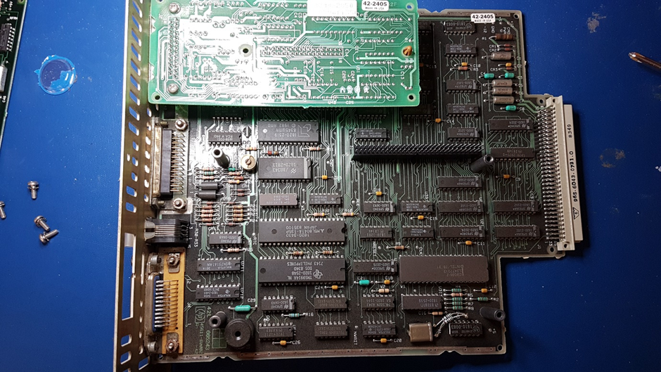
The graphics card pulls out fairly easily from the “front plane”. As is often the case with card cages, it is almost impossible to instrument the card without an extender – which i don’t have.
The manual doesn’t go down to the chip level, but the error code looked like it might. Probably an error bit for each of the 8 bits of GRAM and 1 bit for the bank. That made it the 6th bit of bank 0.
I could see two bad vertical lines on the screen – one was flickering, and the other was solid. They were repeated across the screen. I wired up quite a wide ribbon with alternating signal and ground to bring the RAM outputs to a scope so I could check with the board in place. I found two lines that were different from the others – bit 6 on both banks.
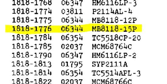
I cut out the first RAM and replaced with a socket and 6164 DRAM. The 16k DRAMs are compatible with 6164 64kb DRAM. The error codes changed on the 9th bit – the second bank failure. I repeated the exercise and the GRAM errors were cleared.
The manual said that part of the GRAM was used for variables, so I was hopeful that clearing the fault might allow the machine to the boot stage. And it did. I had some work to do on the drives before i could try to boot.
By this stage, the keyboard error had magically cleared. It did re-occur some years later, but i think it was due to a corruption of the configuration data, either due to a program crash or a power cycle. The computer automatically reloaded the defaults after the self test.
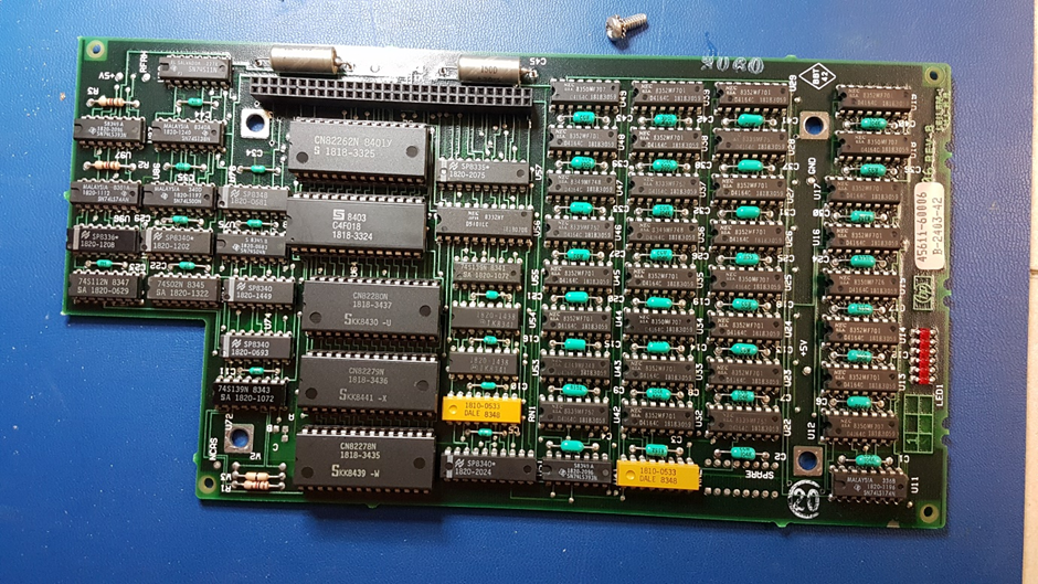
The main processor board is fairly easy to remove from the “front plane”. It has a mezzanine RAM card RAM with 256k of memory.
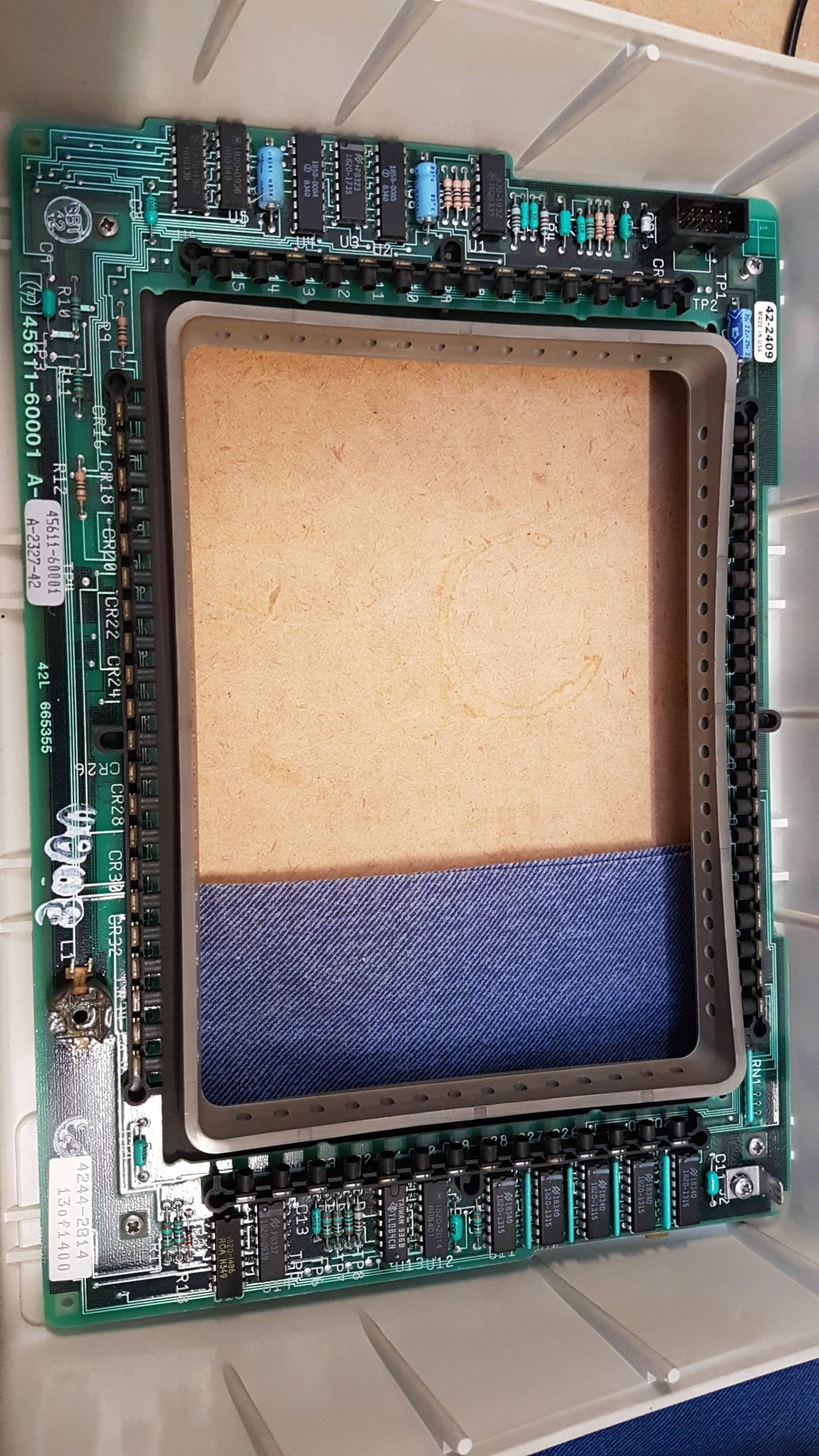
Touch panel:
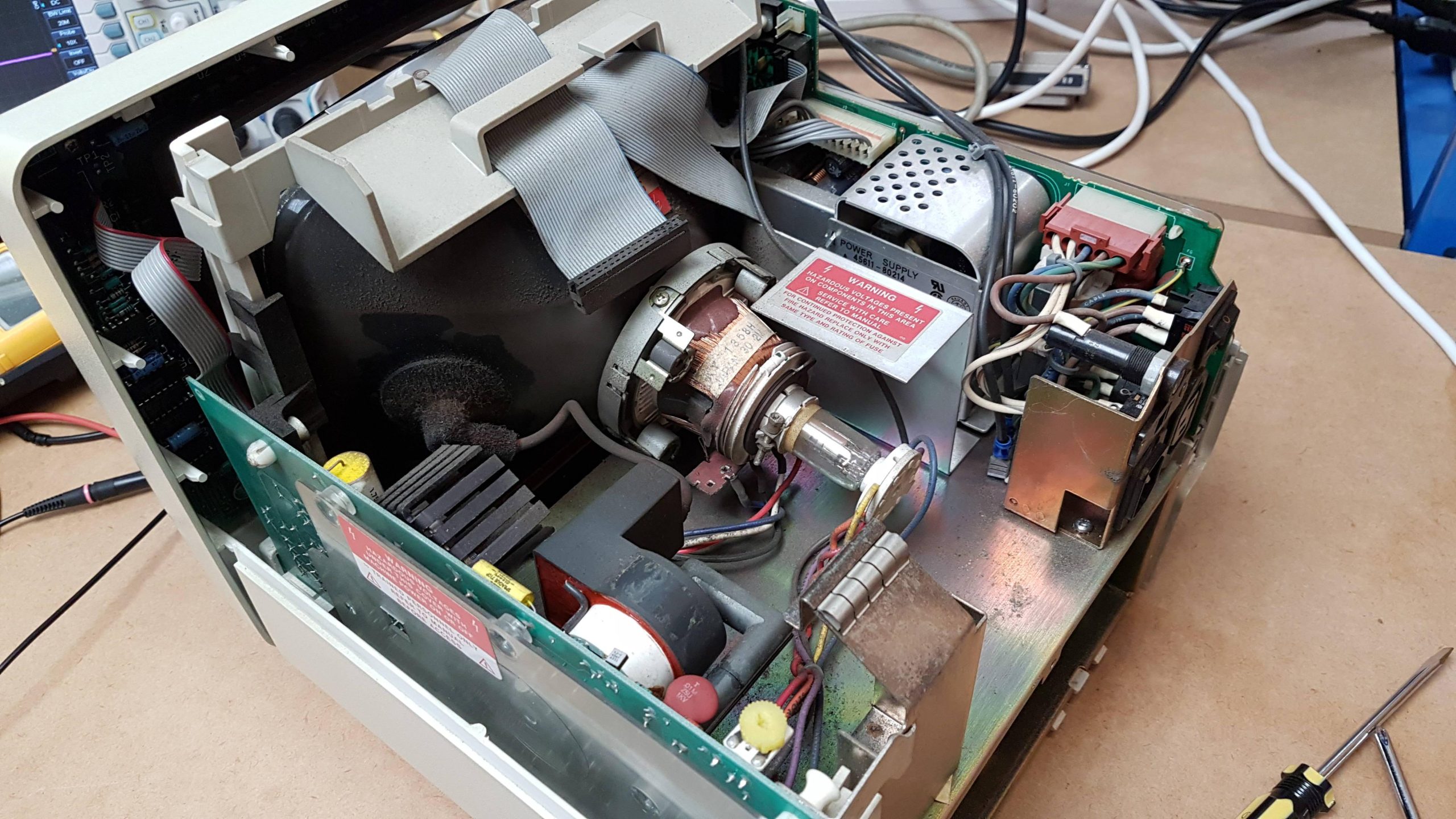
CRT, chassis, and power supply:
I didn’t see anything that particularly worried me.
The HP 150 uses an external 9121 2x Floppy Drive Unit that connects via HP-IB. The drives are Sony OA-D30V-1 3.5″ single-sided double-density 70 track units. HP was a very early adopter of the 3.5″ disk format.
The drives were quite gummed up. I cleaned and lubricated them, and they were good to go.
The unit came with several disks, but it wasn’t necessary to use them. There are lots of disk images available at the HP Museum:
The images are in either Teledisk or HPI format. I had limited success writing Teledisk images using Teledisk on a PC. Perhaps the drive wasn’t configured for double density disks.
I did better using HPdrive (also used with the HP 85). HPDrive uses HPI files rather than TD0. These seem to be similar to raw image files. The TD0 files were converted to HPI format using a utility, TD2HPI.
I found that the 9121 drive option seemed to not work very well. The 9122 supports double-sided disks and uses the SS-80 protocol rather than the Amigo protocol. Perhaps a little incompatibility in the amigo protocol.
HPDrive reported that all the images were the wrong size – perhaps because it’s a double side drive. They worked though.
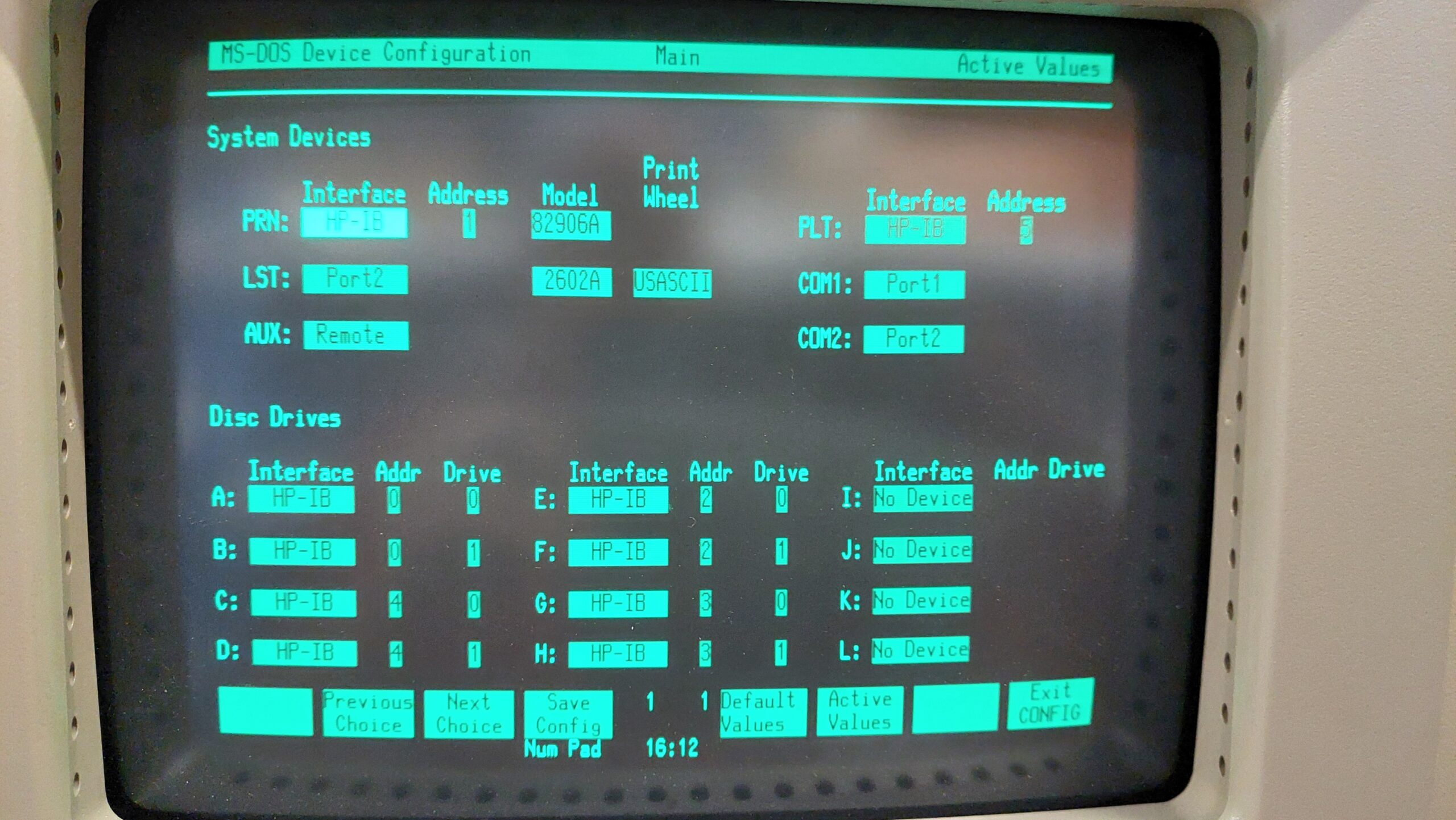
Devices need to be configured using “Device_Config” on the system disk. The boot drive is fixed as HPIB address 0 drive 0. This is drive A:. For the 9121 unit, drive 1 is B:.
The HP150 can also use the 82901M drive unit that i use with the HP 85. I’ve set the 82901M drives at HPIB address 2. These are drives C: and D:.
The 82905B Printer is set to HPIB address 1.
The following creates a -9122 drive at HPIB address 3.
Hpdrive -l 3 -a 3 -9122 <filename>.hpi
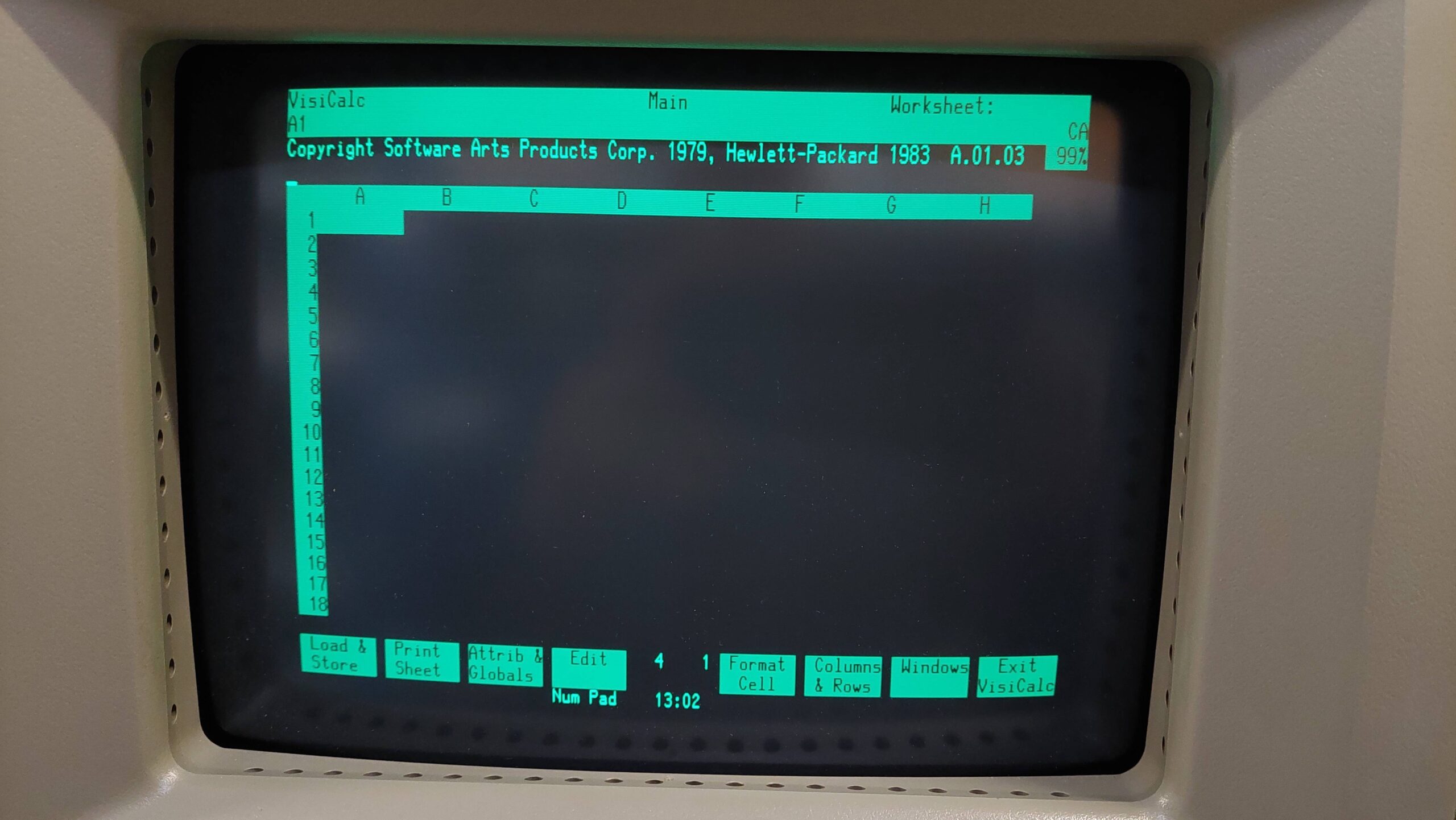
The system disks use MS-DOS 2.01, but don’t have the full collection of programs that would normally come with the OS. The Owner’s Guide indicates that some programs are relegated to the Programmer’s Pac disk. This disk image does appear to be on the HP Computer Museum site, but the image is corrupt.
The disks need to be formatted before use, and that seems to be the only way to set the disk label – so you can’t just format a batch and label later.
Amongst the disk images on the museum site was a hard disk image with MS-DOS 3.2. I was able to boot from that and create an MS-DOS 3.2 boot disk with a few more programs.
To boot from the image, the hpdrive has to be at address 0 and the physical 9121 drive unit must be reconfigured to a different address. eg:
hpdrive -l 3 -a 0 -9134D 150loaded.hpi
The system needs to be completely restarted if the drive address is changed.
There is no way to copy a complete disk track by track.
It seems that distributed disks are “uninstalled”. There is an installation program on the Applications disk, that allows programs to be installed from the distribution disk on to a formatted floppy disk. The installation copies the files over and sets up files for the Personal Application Manager (PAM). This is a program which acts as a shell and activates programs by touching soft function keys.
Some of the disk images on the HP Computer Museum site seem to be installed and some not. Some of the disks don’t follow the HP 150 “formula” and just have software on disk that can be copied over.
In some cases, it seems to be possible to install from an “installed” disk, but in other cases it seems not. Generally it’s possible to copy over the files and they will work. They won’t appear in PAM, though. You have to go to the DOS command prompt to execute them.
HP seems to have used hidden files to manage copy control. The hidden files can be revealed with chkdsk /v but there seems to be no program on the system disk to unhide them.
This brings us to the subject of transferring files to and from the HP 150. The usual suspects are disappointing. Greaseweazle and FluxEngine don’t support the format but can read and write fluxes. Many of the HP formats can be manipulated by HPDir, but it seems that the HP 150 file system is quite different from the HP 9845 file system.
Both the HP 85 and the HP 150 have a curious disk layout where each track has 16x 256 byte sectors and 1x 128 byte sector. Others have commented that the 128 byte sector is not used.
There is an MS-DOS driver, HP150SYS, for IBM compatibles that allows manipulation of an HP 150 disk in much the same way as IBM disks. This driver was written by the author of Teledisk, Sydex. It works well.
Files can also be transferred over a serial line using Kermit. The disk image for Kermit is a 720kB image, but i could access it by setting the drive type on HPDrive to a double-sided disk unit. Then the files could be copied over to some single-sided disks.