The 7803 is a Z80 CPU card with 1k of static RAM expandable to 4k and provision for 8k of ROM as 4x 2716 EPROMs.
This board carries an MP4 monitor ROM which operates with a 7303 Keyboard & Display Card. That’s a nuisance because i don’t have a 7303. To operate this card, i will either need to find an off the shelf monitor and modify it, or i will need to emulate a 7303.
This card did not have a Z80 IC card, so i have added one.
The 7801 is a very simple 8085A card with 1k of static RAM expandable to 4k and provision for 8k of ROM as 4x 2716 EPROMs.
The 8085A includes a simple serial port, but this card has no level shifters, so the levels are TTL.
Currently, this board has no ROM, but its memory map is the same as the SDK-85, so its monitor ROM may be suitable.
Pro-Log also developed a monitor ROM. I have a copy of this ROM, but it relies on having the 7303 Keyboard & Display Card, and i don’t have one. I have ordered some STD prototype cards with a view to creating a 7303 emulator.
Intel SDK-85 monitor ROM was suitable. It uses the 8085 serial terminal for user interaction – albeit at 110 baud (with 7 bits and no parity).
The SDK-85 monitor checks the state of the RX line on startup. If it is high, then it will use the SDK-85 keypad and seven segment displays (which the 7801 does not have). If it is low, then it uses the serial lines.
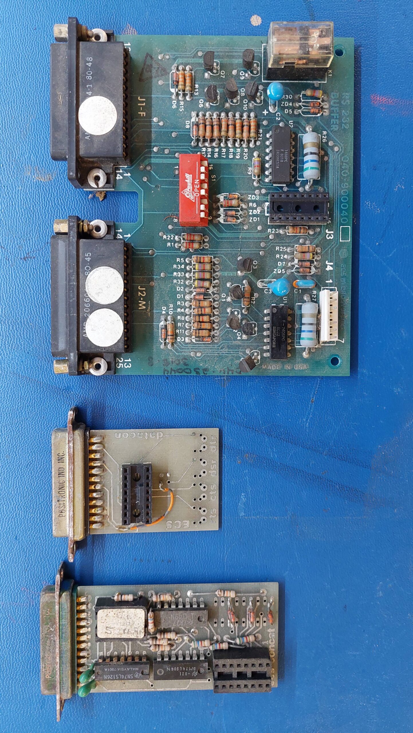
The 7801 does not include level shifters, so i removed a couple of ICs from a 7301 RS232 card, so i could use it to do the level shifting.
This was sufficient to show that the 7801 card is quite viable.
Rather than use such cumbersome level-shifting arrangement i thought a little TTL-RS232 converter off ebay would be a bit simpler. It did not go as smoothly as expected ….
It turns out that my test setup was somewhat fortunate in that the transmit line was not inverted. It seems that the serial transmission using the SDK-85 ROM is inverted with respect to the receive. This meant that i had to modify the 7801 to remove the TTL-TTL inversion at U10 (74LS240). This meant lifting pin 3 out of the socket and then connecting pin 17 to pin 3. I also had to add 5V to one of the unused pins on the connector socket, J1, so that i could power the level shifter. I used pin 8.
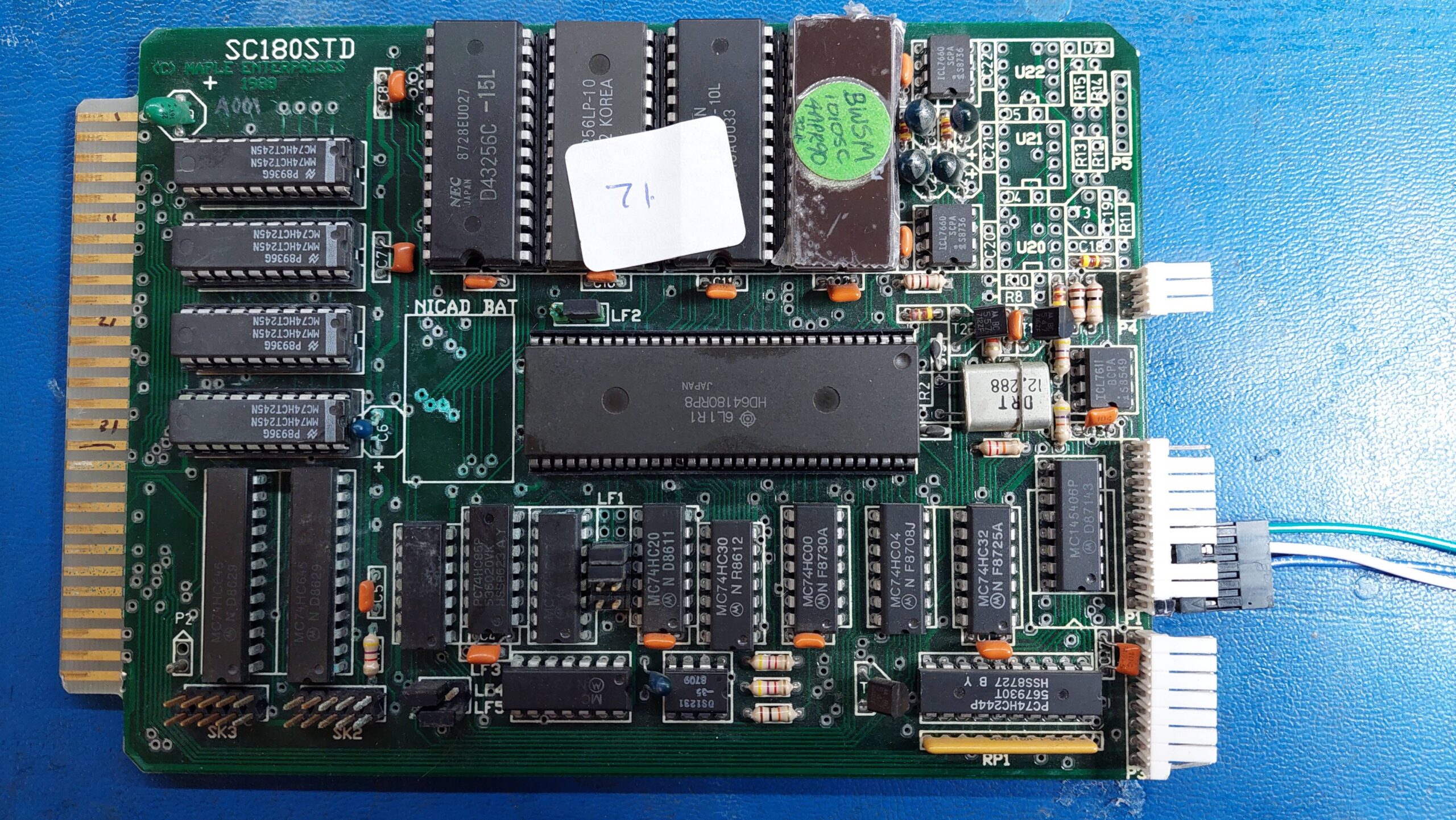
This card uses a Hitachi 64180R microprocessor, which is a direct replacement for the Zilog Z180, which itself evolved from the Z80 microprocessor.
The card was made in about 1988 and is branded with Maple Enterprises. I have not found any information on this company. It may have been related to Maple Systems, which currently manufactures industrial computing equipment.
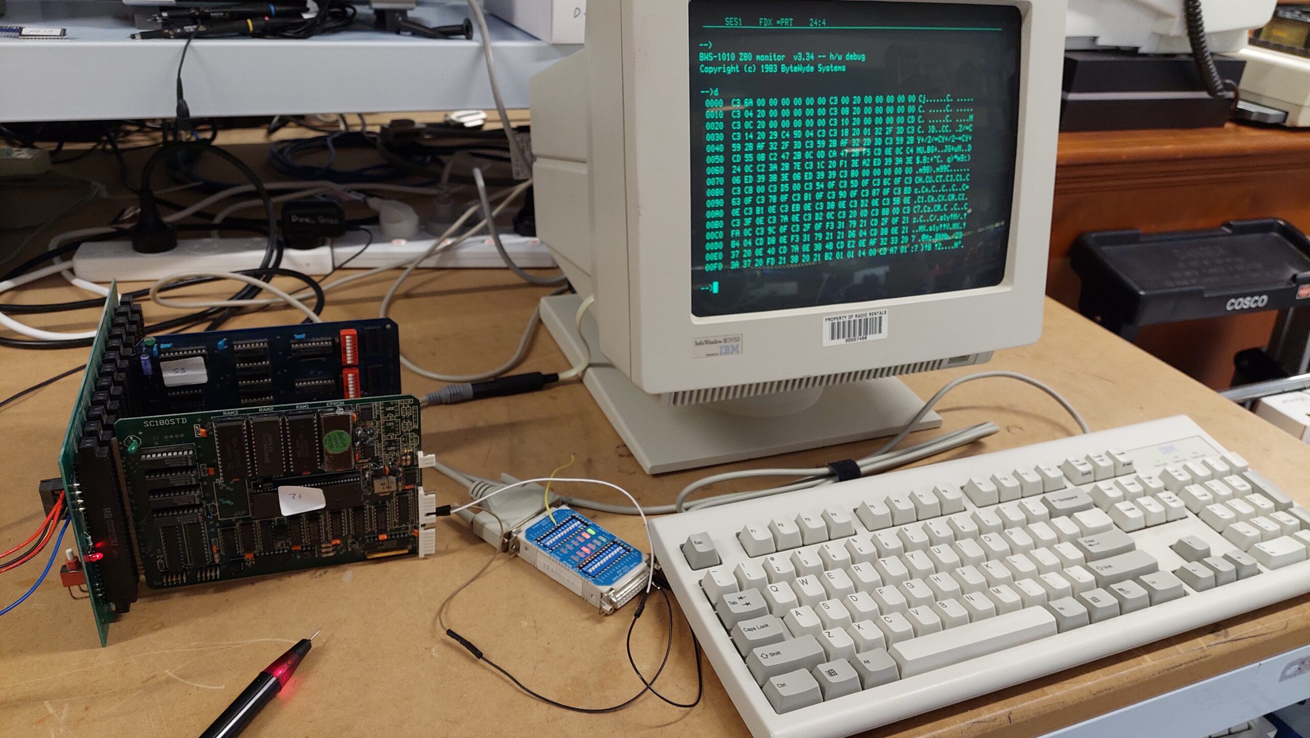
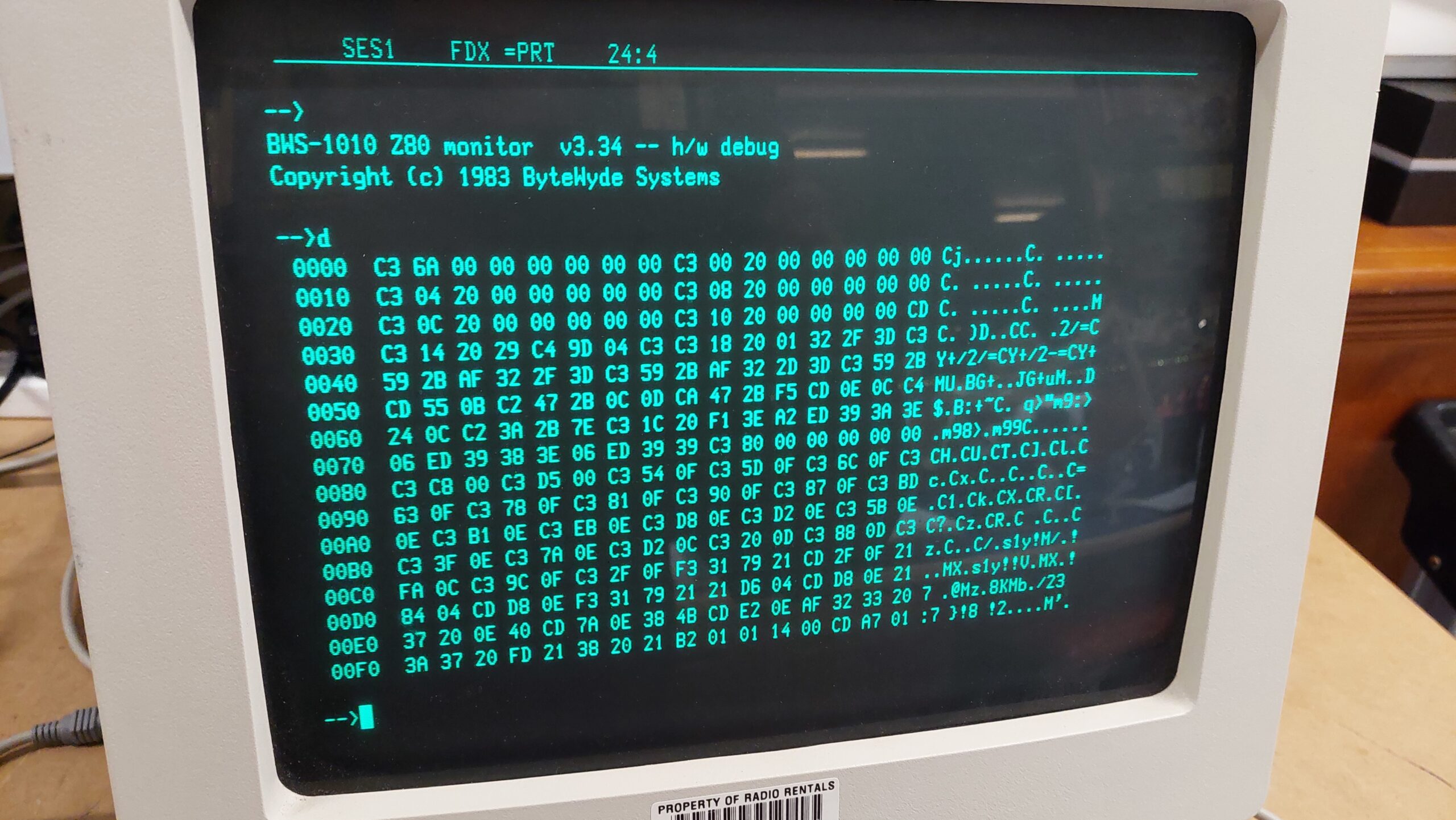
The processor includes two asynchronous communication controllers. Fortunately, this card has a serial monitor in EPROM. The monitor program is the 1010SC ByteWyde Systems. The ByteWyde monitor was customised for various systems. I was able to find a manual for a similar version.
ByteWyde probably also customised their BASIC for this board, but i do not have a copy of it. Sigh.
I have no documentation for the board itself, but it is clear that the card has a 16k ROM and 48k of static RAM. At one time the RAM was battery backed, but the battery has been removed. There is a little residue from the battery leaking which will need to be cleaned up. [I subsequently found a schematic in amongst some old notes.]
The memory space can be positioned on any of four 64 byte blocks. The monitor assumes that it is at 00 to 3F. I would probably need to change the base address on some cards to use this card.
I was able to work out the serial port pinout for tracing some signals from the processor. The board has a 20 pin footprint for the level shifters but the MC145406 only has 16 pins and is offset by two positions from pin 1. To further complicate matters the board has been modified P1-5 is grounded (not DCD) P1-2 is DCD (not 9V), P1-6 and P1-7 have been shorted so that RTS and CTS are connected on the board.
P1-3: Rx
P1-4: Tx
P1-5: Ground
After a little clean and re-seat the card came up fine. Serial port is 9600,8,N,1.
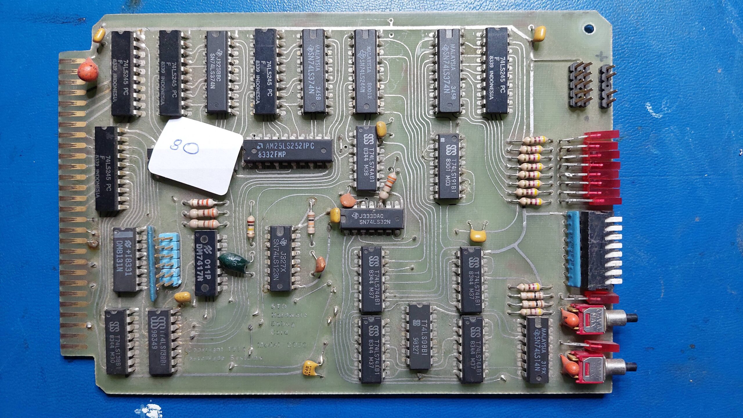
The manual for the Monitor mentioned that some commands require the use of a ByteWyde Hardware Debug Card. As it turned out i had one of those in amongst my cards. I suspect it will need a good clean before use.
The Microlog MC52 is an STD bus single board computer that uses an Intel 8052AH-BASIC microcontroller. This microcontroller includes a masked ROM containing a BASIC interpreter.
I have not been able to discover much about Microlog, which is a shame because they were a local Adelaide company.
Based on IC date codes, the board was manufactured around 1988. It includes 32 of static RAM, an EPROM socket, parallel port, programmable interval timer, and a serial port.
User interaction is via a terminal connected to the serial port. After power-up, the operator has to type a couple of spaces so that the baud rate can be detected.
I have no manual for this board, but i expect that it is similar to one of the configurations described in the Intel MCS BASIC-52 User’s Manual, eg the one in Figure 2A.
It clearly has some differences, including the STD interface and a P8255 Peripheral Interface – probably connected to the 40 pin connector on the front of the card.
One of the unusual features of this BASIC is that the interpreter allows programs to be stored in and executed from EPROM. Looking at the board, the programming voltage seems to come from an external supply.
I thought this card may be quite handy for testing some of the STD cards that i have, but i will need to work a few things out first, including addresses. The STD bus has an I/O space, but i don’t think the 8052 has such a thing, so i’m guessing it’s mapped into memory somewhere. So i did a bit of buzzing out ….
I found that the top 3 address lines are decoded into 8k chip selects. The bottom 4 (0,1,2,3) are used for the 8k static RAM chips (HM6264). The next two (4,5) are used for the EPROM so it can be a maximum of 16k ie 27C128. The next one (6) is used to enable the second decoder. The last one (1) selects the STD bus I/O space. There doesn’t appear to be a mechanism to access the STD memory space.
0000-7FFF
Static RAM
8000-BFFF
EPROM
C000-DFFF
Second decoder
E000-FFFF
STD I/O
C000-C0FF
8255 Programmable Peripheral Interface
C400-C4FF
8253 Programmable Interval Timer
The second decode breaks C000 to C7FF into 8 x 256 byte spaces. These are mirrored in the remaining space.
External memory is accessed from BASIC using XBY “function”. I tried the Pro-Log 7601 Input/Output Card and was able to read and write the registers at 00-03 using XBY(0E000H+i).
I also briefly tried the 7301 Serial Card which registers at C0 and C1 using XBY(0E0C0H+i). That also responded as expected.
The MC52 is definitely useful for testing I/O boards. Memory cards are a different problem.
Many Australian computer manufacturers have come and gone, and many of those have left remarkably few artefacts by which to be remembered. This is often the case with business oriented companies such as ECS Microsystems (later TIME Office Computers).
This machine belongs to Michael N from the Adelaide Retrocomputing Group. Michael is in a position where he is able to intercept treasures such as the 4500 before they depart this world.
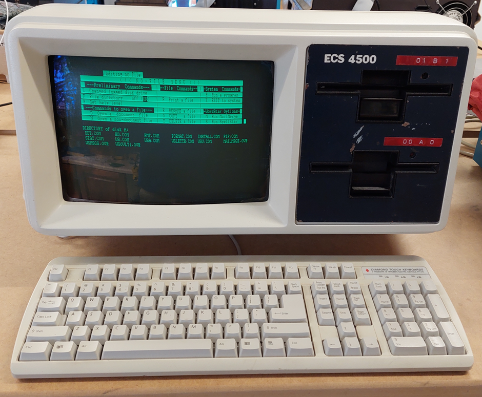
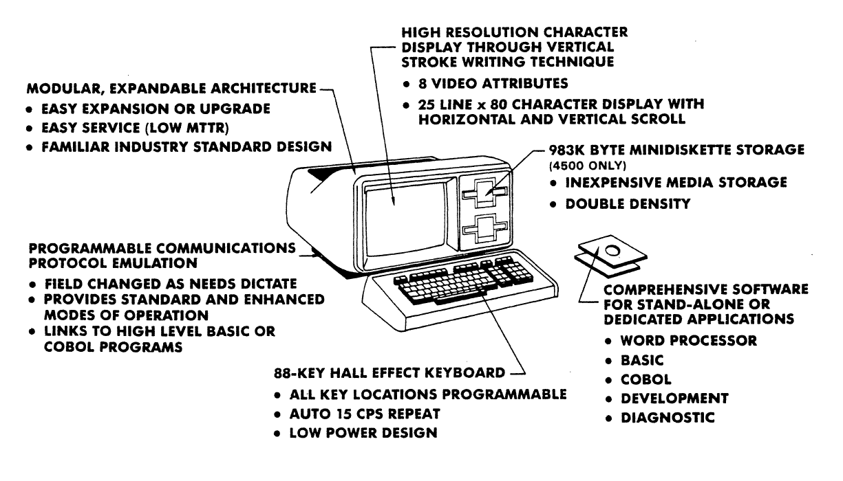
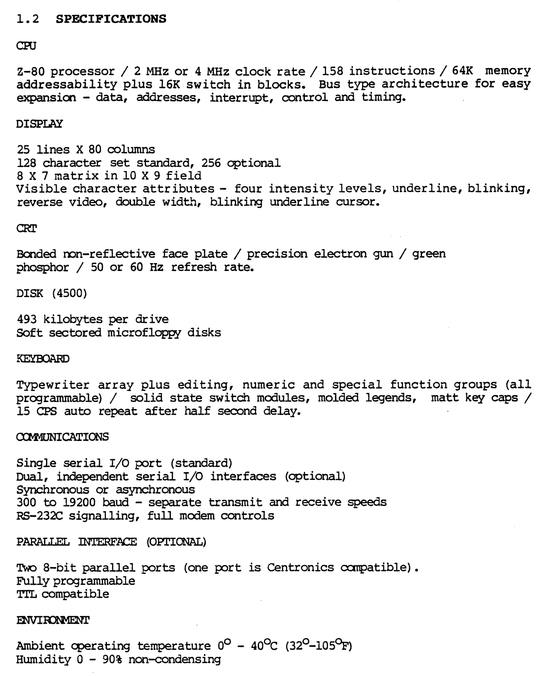
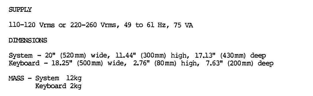
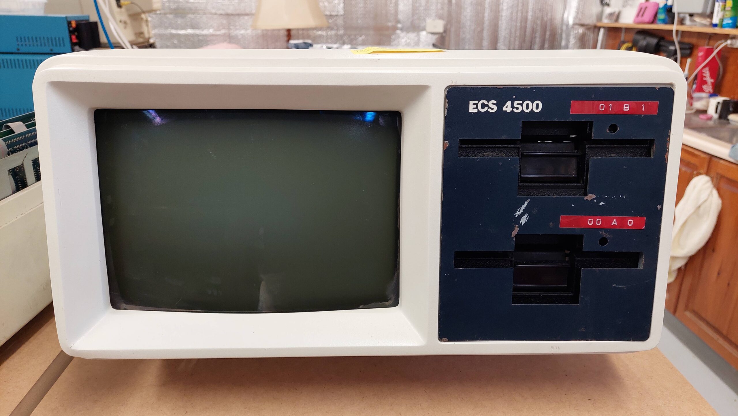
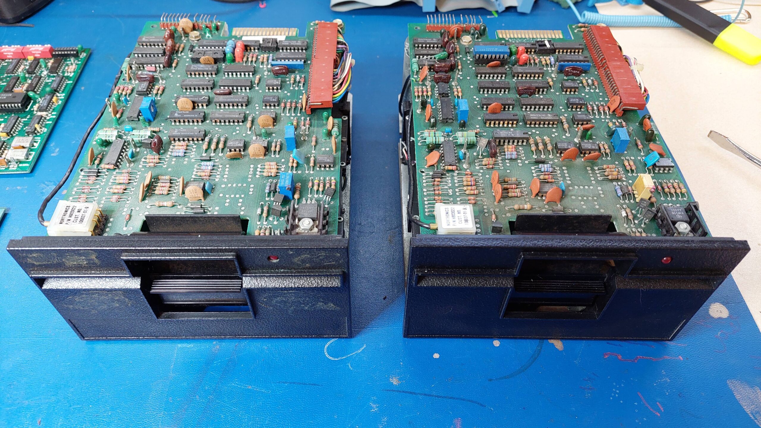
The ECS 4500 is a CP/M machine from about 1984. It uses a Z80 processor, has 96kB of RAM, and uses two Micropolis 77 track double-density 5.25″ drives (with a curious mod that i discovered).
The ECS 4500 is notable for the way it generates characters on the CRT and for its unusual disk format. More on these to follow.
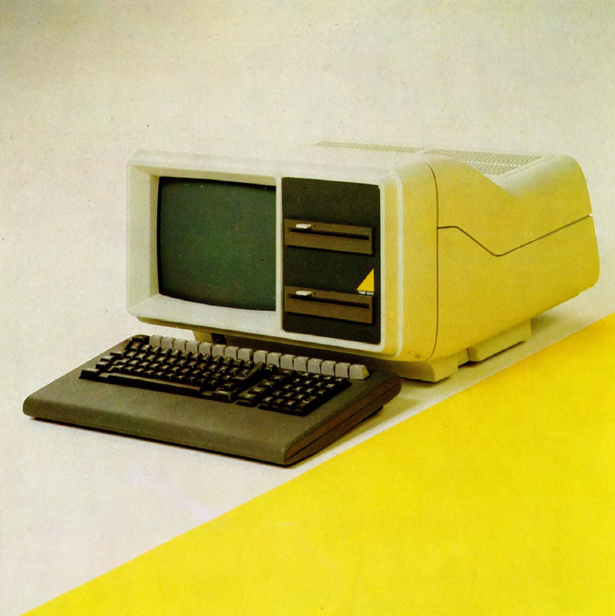
Perhaps a slightly later version here with different drives and keyboard:
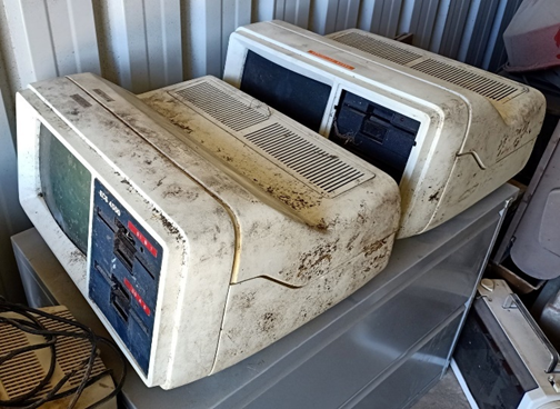
Michael rescued two of these machines when they were pretty down on their luck:
As is often the case with computers that had detachable keyboards, the keyboards had been lost.
Fortunately, they did come with some manuals:
ECS 4000 Series Technical Manual
ECS 4500 Operating Guide
Time 4550 Operating Guide
These have been scanned, and Alan Laughton has uploaded them to the Microbee Technology File Repository under Repository/Vintage/Time_Office:
Most importantly, the machines also came with disks, images of which have been added to the above repository.
Michael has been very generous to me and many other club members, and i really wanted to have a closer look at these machines anyway, so i set about getting one operational.
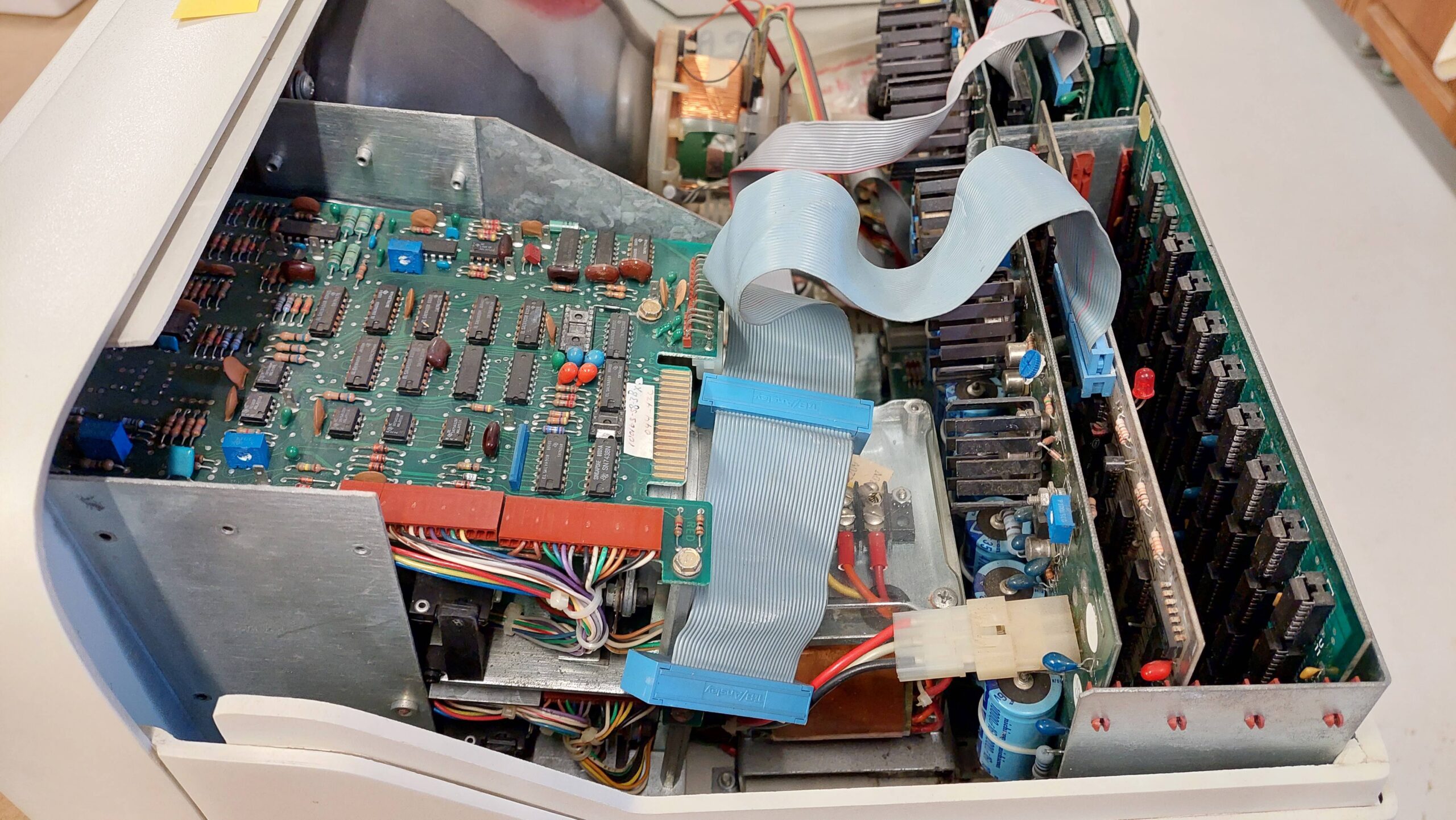
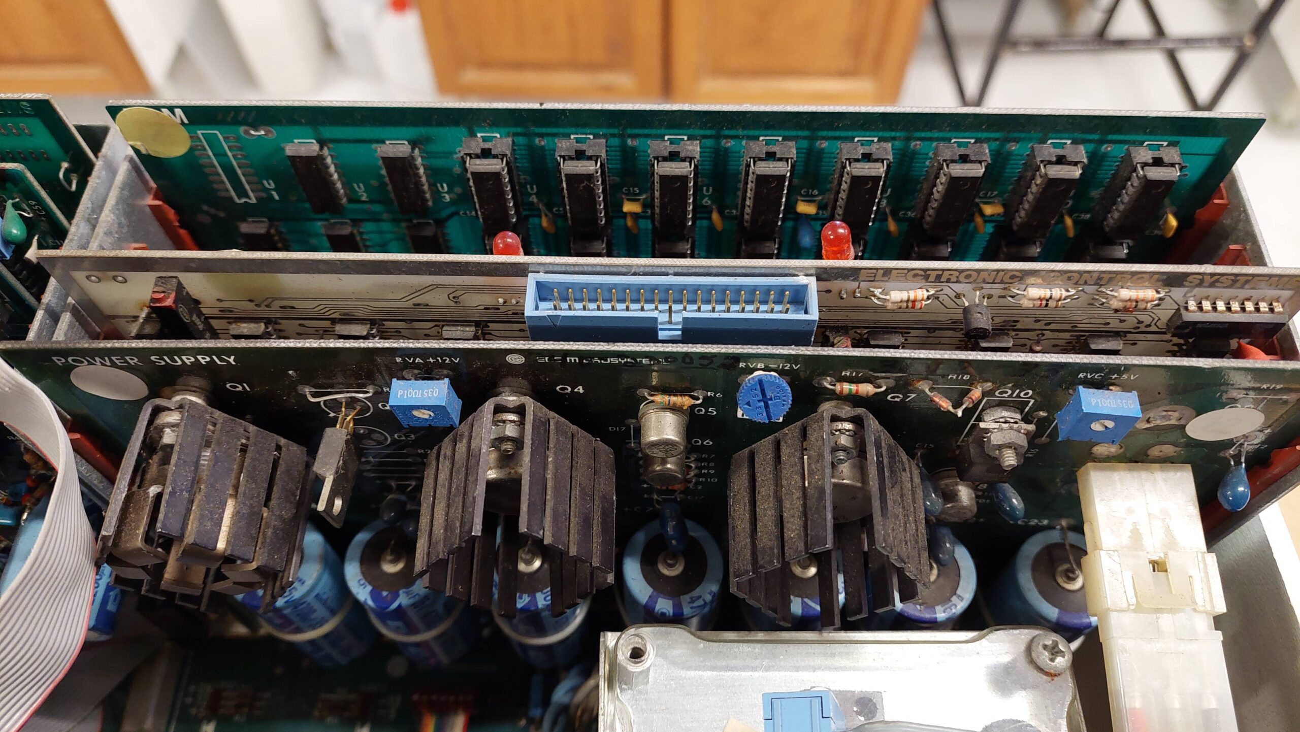
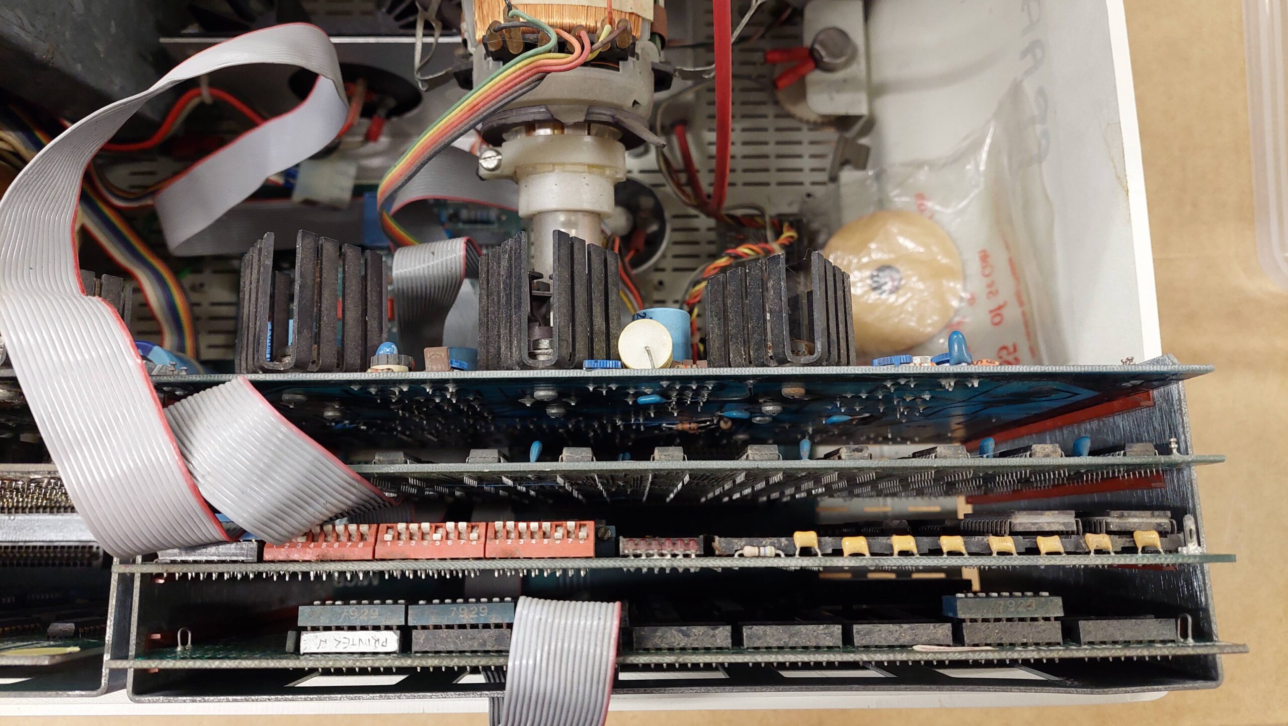
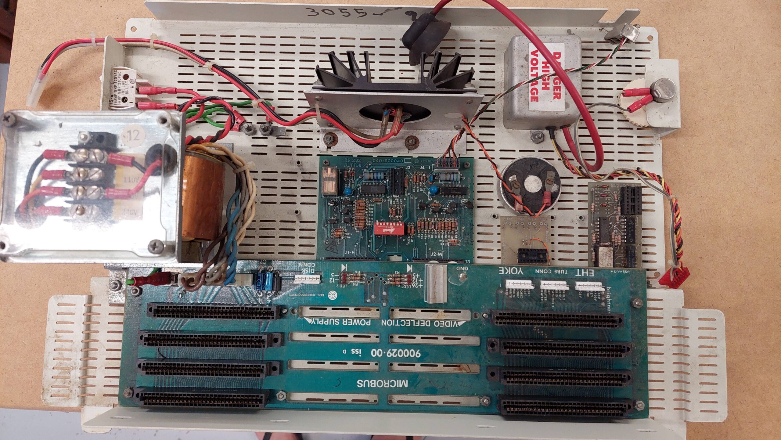
The design is quite neat, with the plastic chassis with drives and CRT lifting off the rest of the system, which is mounted on a steel baseplate.
There is a card cage at the rear with two special slots (Power Supply Board and Video and Deflection Board) and 6 general purpose slots with:
Processor card
Memory Card
I/O Card
Video Control Board
Floppy Disk Controller Board
The slots are arranged as two columns of 4 cards.
The video deflection card was missing from the second unit so that put restoration of that machine out of reach.
There are additional I/O adapter modules at the bottom of the unit on an inset fascia.
Also mounted on the baseplate are:
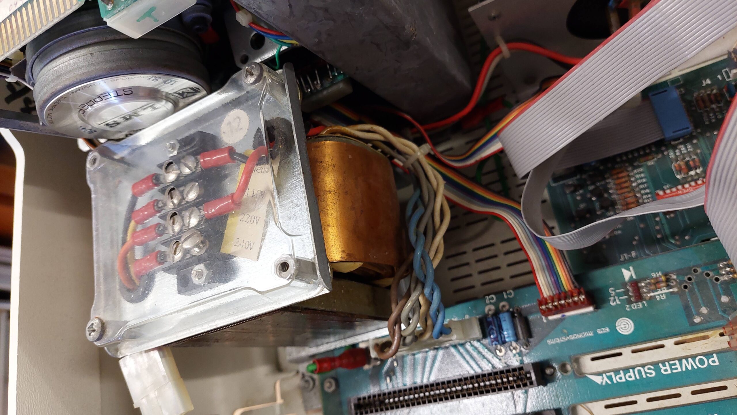
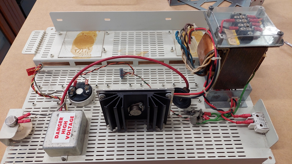
A transformer/terminal block for the linear power supply
Power switch
A 5V regulator on a heatsink
An anode voltage power supply for the CRT
A small speaker
Brightness control
The earthing approach looks solid.
The transformer appears to be in good condition. It has a terminal block for setting the line voltage. This was set to 220V, but I have moved it to 240V to make life a little easier for the power supply. Perhaps there was a reason for pumping up the voltages, but the supply outputs look ok.
There is a power indicator for each supply on the backplane.
The +26V was a little high.
The drives are Micropolis 1015-2 77 track units similar to the ones on my Exidy Sorcerer.
There are a total of 7 cards in one machine. The Video Deflection card was missing from the second unit.
Resto Unit
Spares Unit
Description
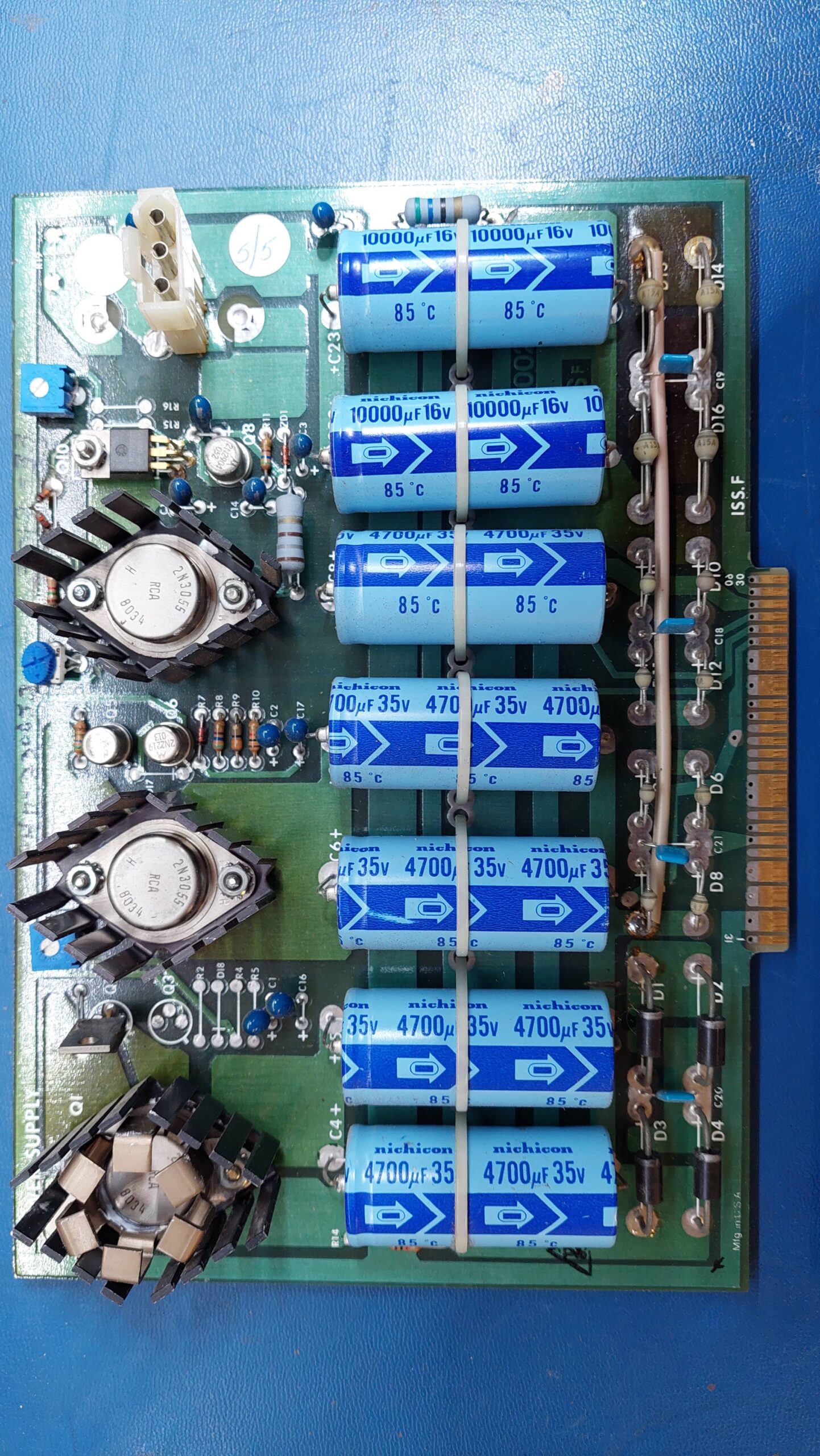
Power Supply
Early Variant
Late Variant
Provides 5, 12, -12, -5, +26V. Note that the 5V regulator is mounted offboard on a heatsink at the bottom of the unit.
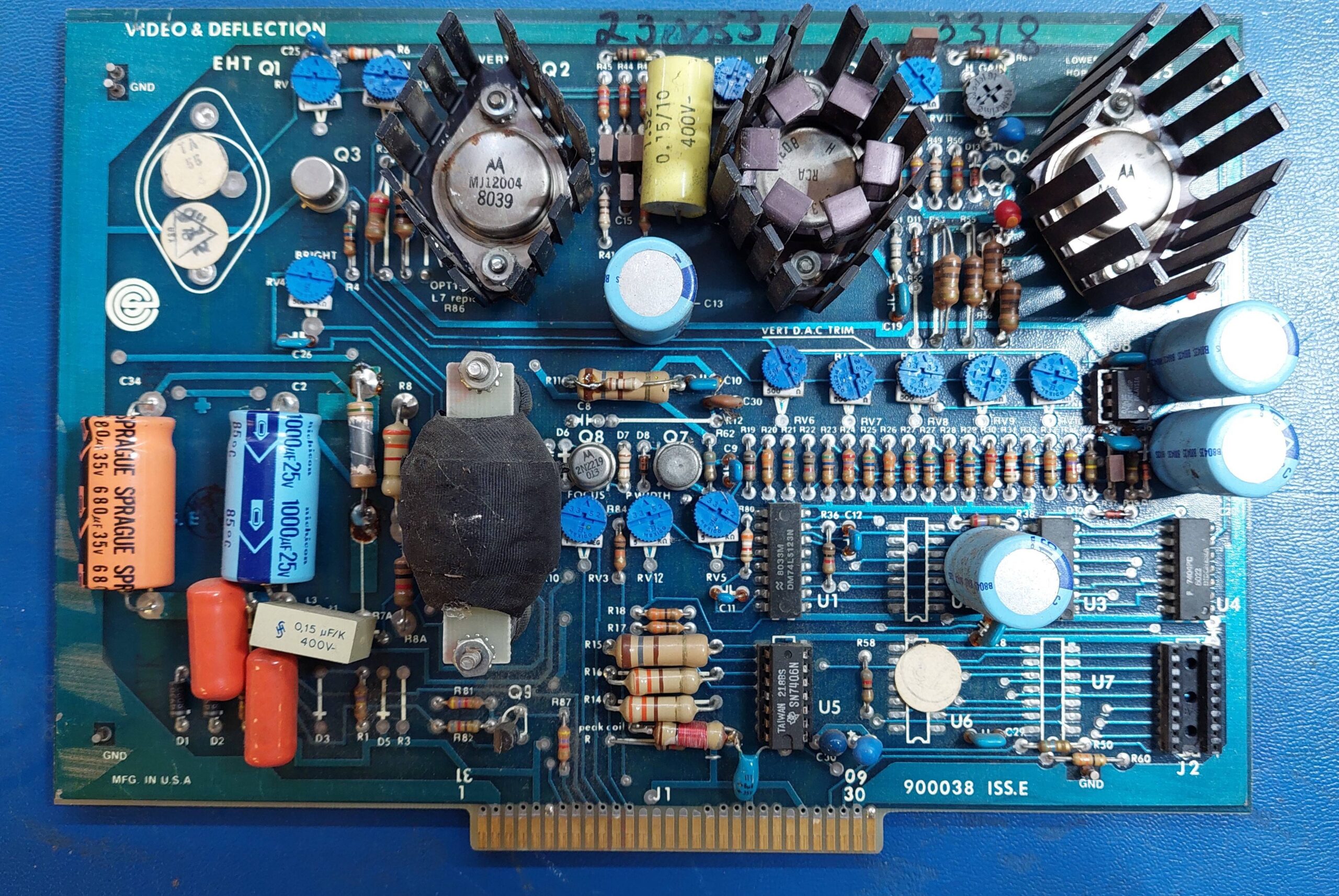
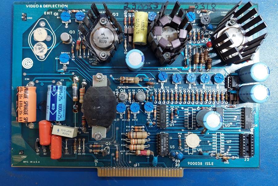
Video & Deflection
Missing
This provides all the analogue stuff for the video display. It’s quite unique. It’s also very rough with a lot of mods.
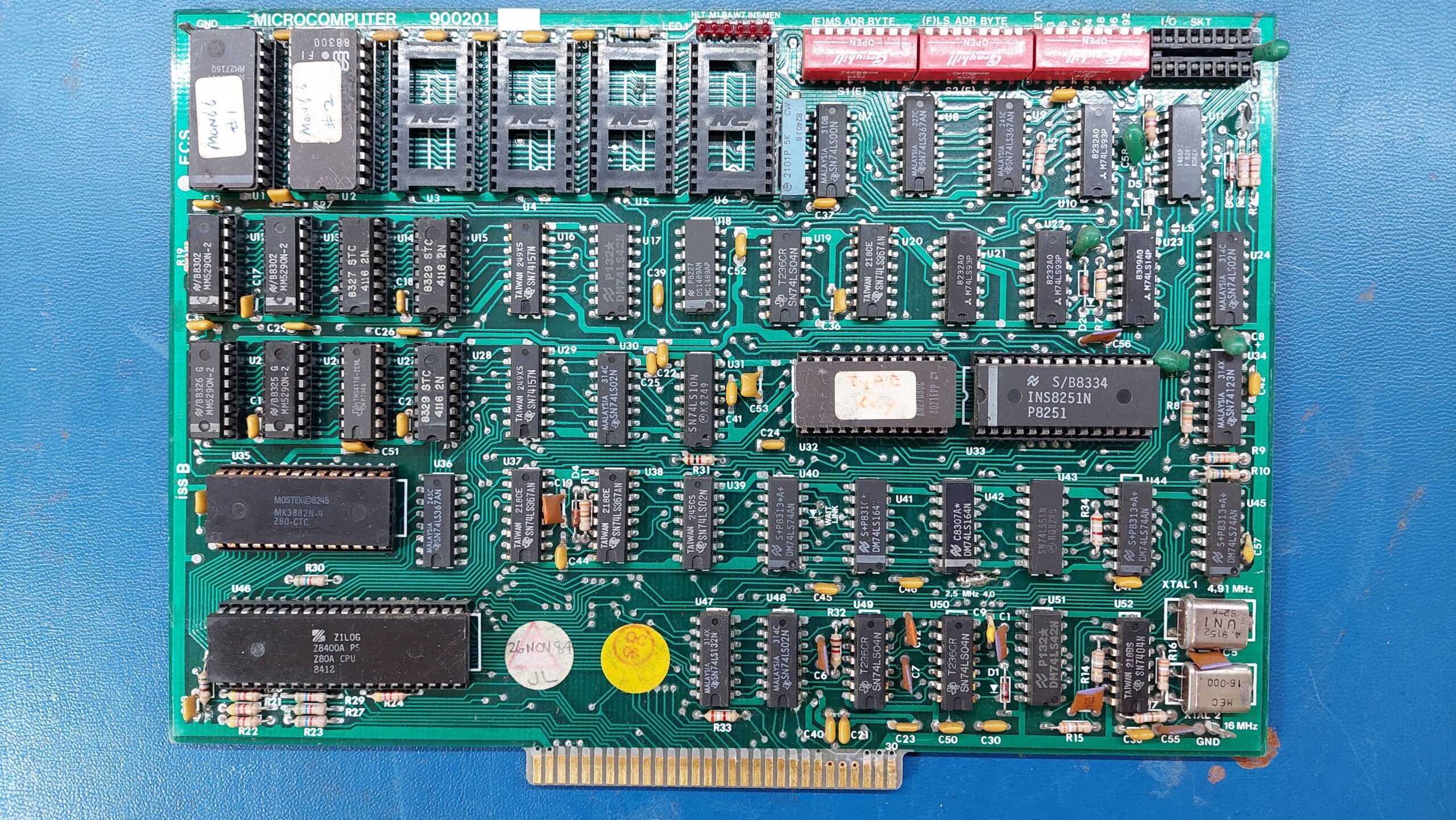
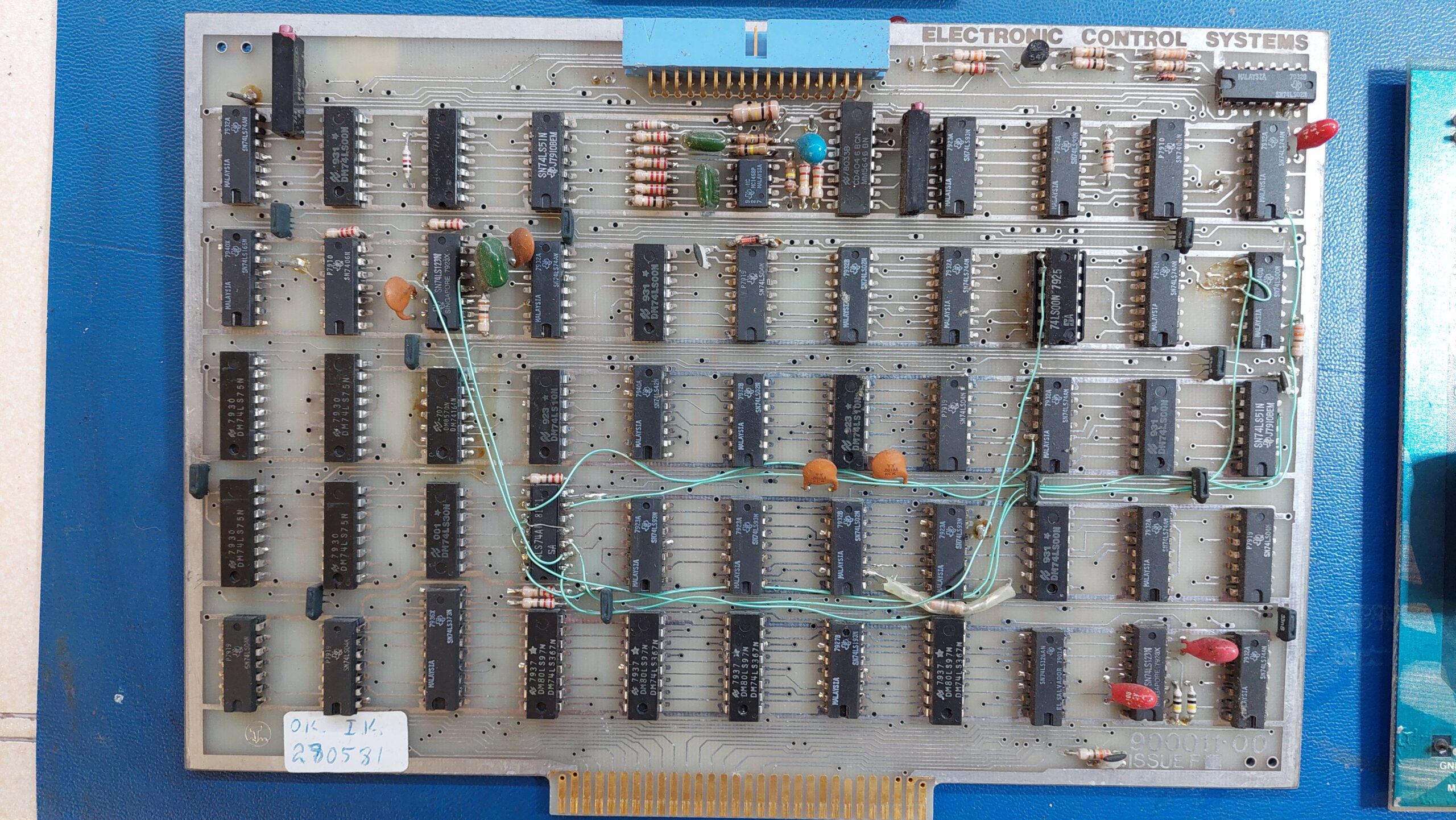
Microcomputer
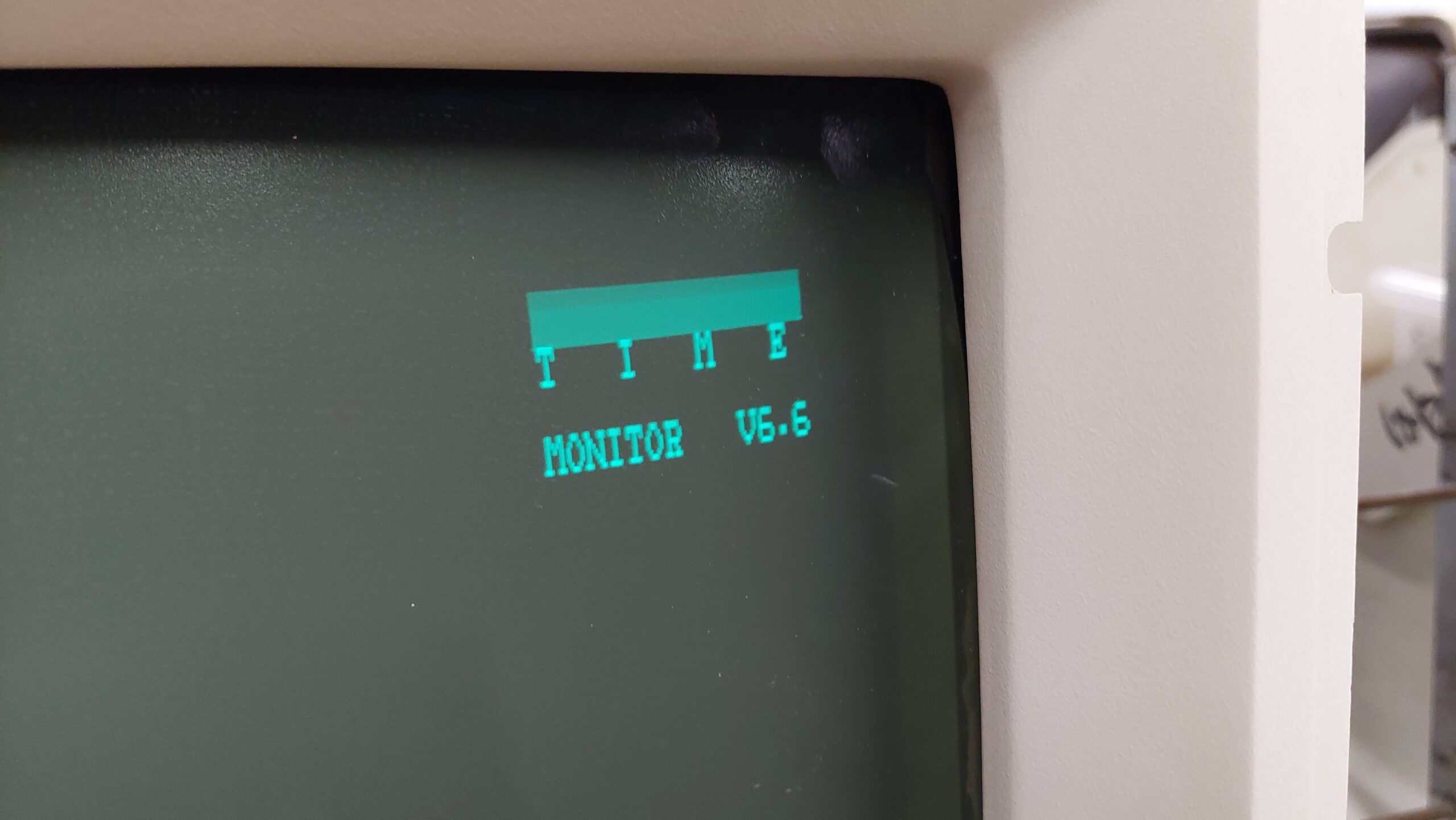
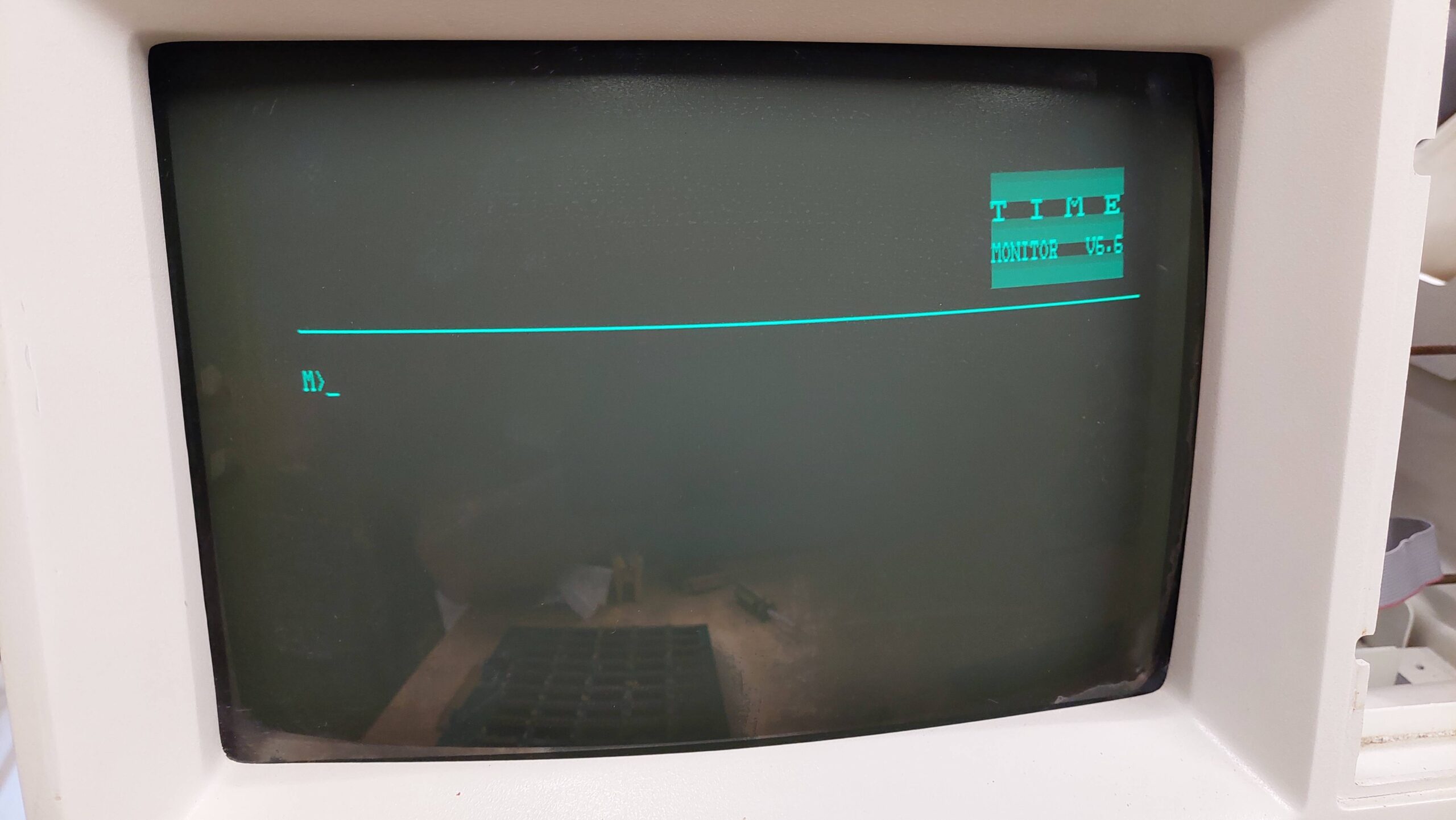
Z80 processor, 8051 UART, 2716 ROMs and 16k RAM that can be switched in place of the ROM. The monitor will come up with just this card and the two video cards.
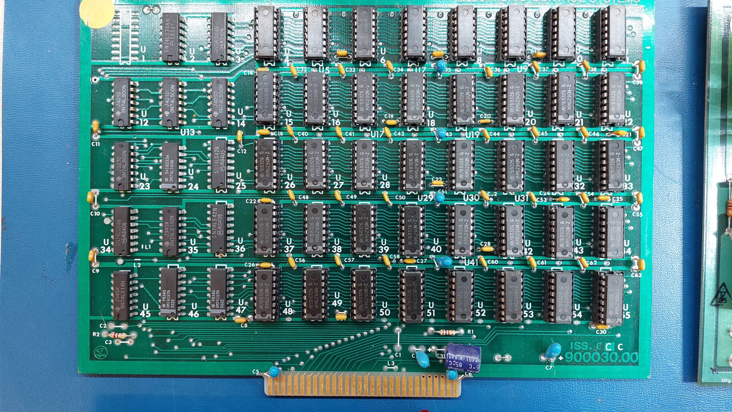
RAM
80k DRAM.
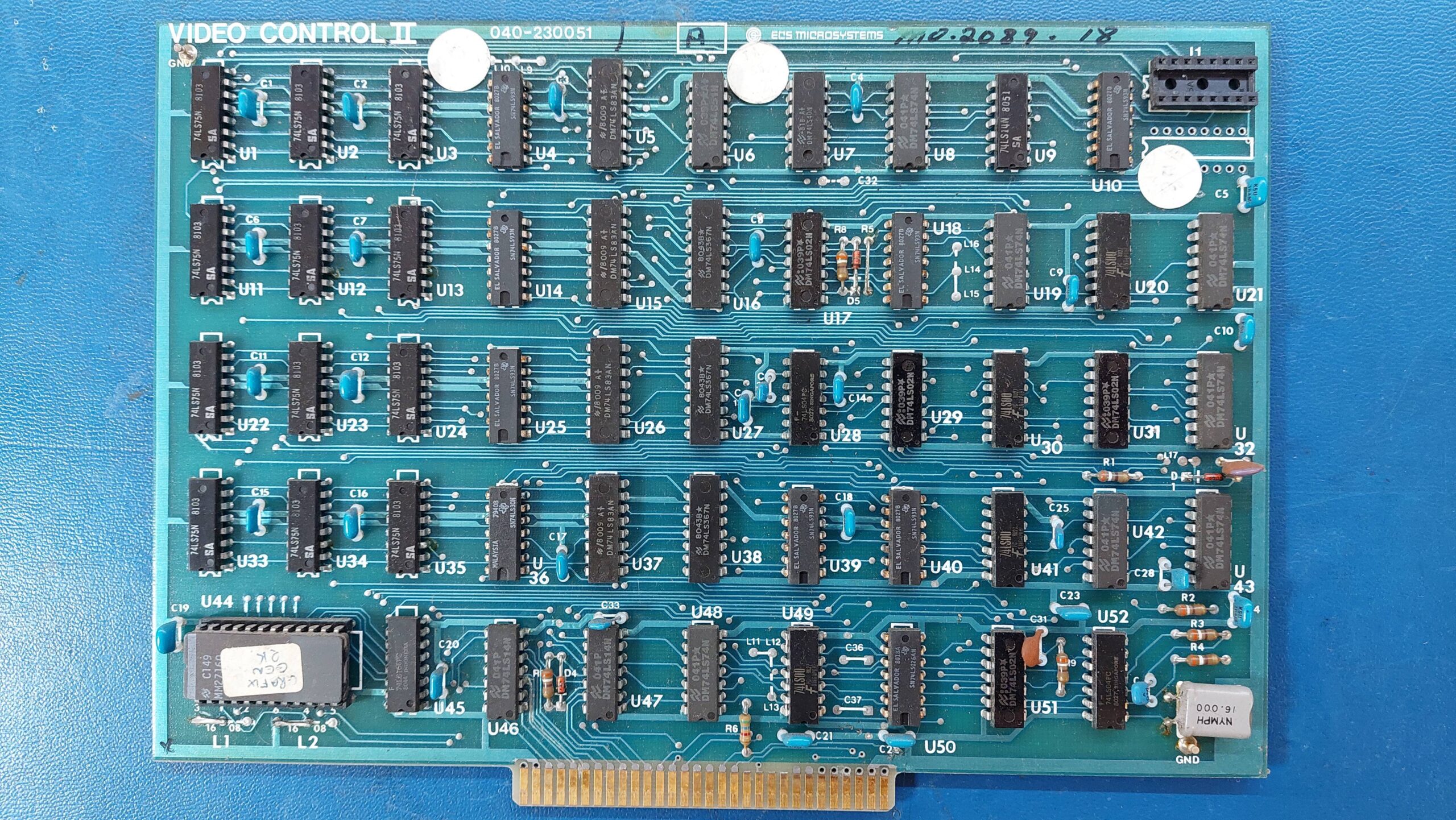
Video Control II
All the digital stuff to produce the video signals. No memory – it DMAs from main RAM.
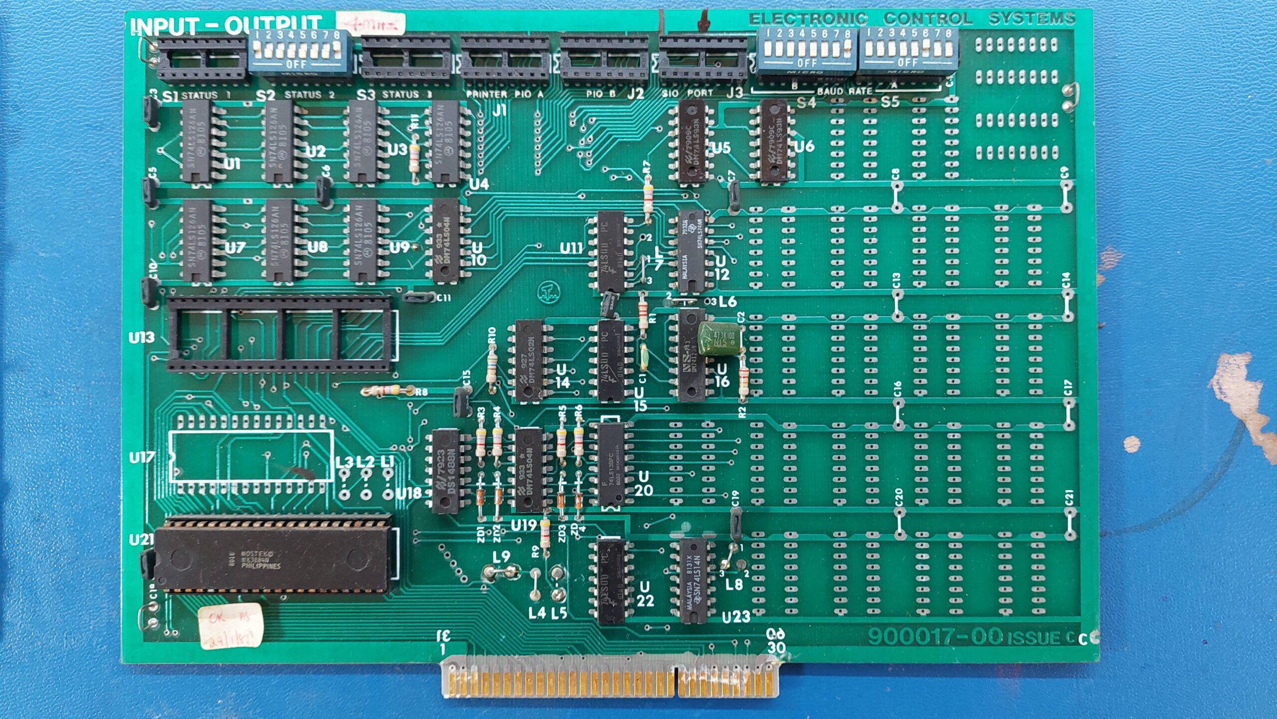
Input/Output
Missing Z80APIO
Has Z80APIO
Provides parallel and serial ports. The parallel port chip is missing from one card.
Floppy Disk Controller
Bespoke floppy disk controller card. Writes a unique format.
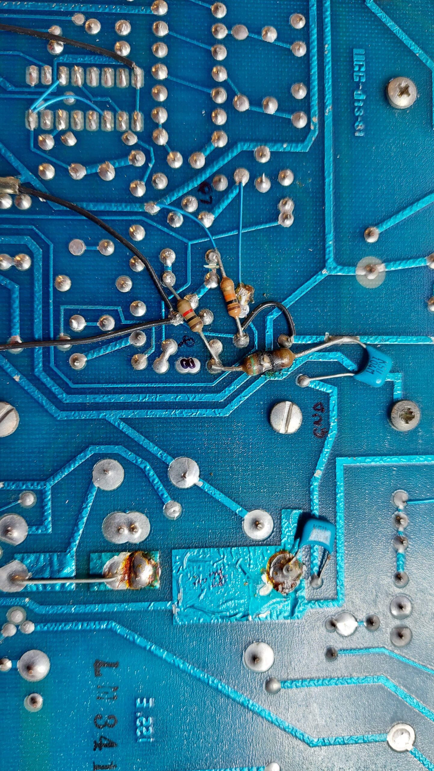
Powering on the system quickly brought a stream of smoke from a resistor on the back of the Video & Deflection Board. The system can only be powered on for a few seconds at a time.
On closer examination the board has had a lot of mods. There are multiple track cuts, added components and changed components eg a resistor in a diode location.
There are no schematics, but there is a service manual. It has some block diagrams with some references to part IDs and some useful circuit description. It clearly indicates, though, that the high voltage circuitry changed a lot after serial number 10000.
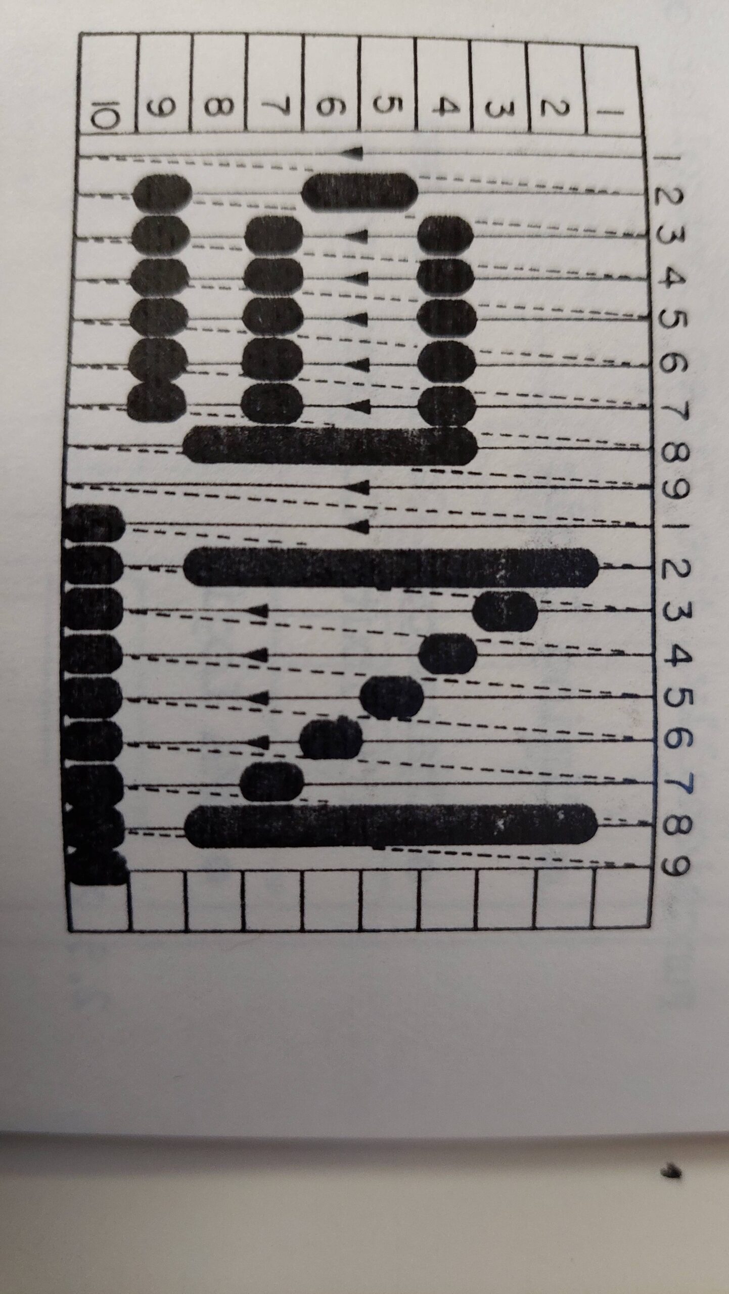
Video control is unusual. Most CRTs use two deflection coils. The scan slowly downwards and quickly horizontally. Characters are formed progressively as a character line.
This system uses three deflection coils. The vertical deflection is performed in 25 steps under the control of a digital to analogue converter. Fly back is very fast: it can happen in the same time as the horizontal flyback.
Within each of the 25 lines each character is formed individually (I wonder if the lexitron does the same thing) using a series of vertical strokes.
This means that there are three deflection channels:
Vertical: 50Hz in 25 steps with each step lasting 800us.
Horizontal: Each sweep corresponds to one vertical step ie 800us.
Write: Quick – 1.06Mhz
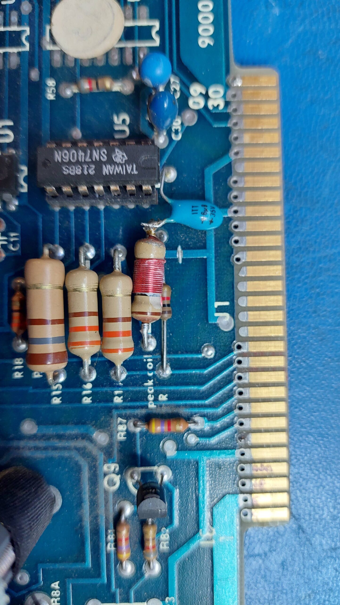
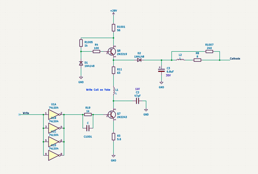
The hot resistor was tacked on to the back of the board among a bunch of mods. It seemed to be associated with the write deflection circuit. It was not going to make any sense without a schematic. I suppose I could have just started swapping components and I would have gotten there in the end (as it turned out). That’s not a technique that teaches much, though, so I sketched out the circuit instead.
The hot resistor measured 56 ohms and was connected to the 26V supply and to the collector of Q8 which is involved in the generation of the write deflection signal. This circuit had been heavily modified. Part of that mod was to provide a power to the high voltage power supply. It also provides the cathode voltage (not shown on the block diagram in the manual). I found that this resistor continued to heat up even without the writing coil, the tube, or the high voltage power supply connected. That didn’t leave many places for the current to be going – just the unloaded cathode voltage circuit.
Looking at the Cathode supply, the tantalum appeared in good condition and the meter didn’t show a short. Putting it on a power supply did reveal a fault with a little more voltage. The tant was replaced with a couple of electrolytics and the burnt resister was replaced with a couple of smaller resistors in parallel.
As a side-effect of this exercise, I learnt about transistors (Q8 in this case) operating in an inverted mode. Nifty.
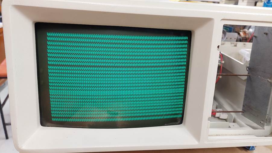
With this resolved, the screen came to life but with a limited horizontal deflection and no vertical deflection. I found that touching pots gave a significant effect and after some cleaning a full picture appeared – filled with rubbish – but that’s a different story.
The vertical step D/A uses a resistive ladder. It has five adjustment pots. It looks like the 3rd bit is not quite right. Actually, they all look like they need some adjustment.
I did discover that some of the heatsinks are live so some electrical screw drivers are a good idea.
Once i got the screen working i was presented with rubbish.
I needed to image the ROMs for posterity, and that also revealed that one of the ROMs had lost its mind. Fortunately, the ROMs in the spare Microcomputer card were good.
With this and some messing around with the onboard RAM, i was able to get a myriad of outcomes, some of which included evidence of the power-on monitor starting up.
The sockets are great and despite cleaning i could not the system to start. I changed to the spare Microcomputer card and was excited to get a monitor prompt.
I added an empty RAM card and started adding RAM, checking as i went. There was only one faulty 4116.
I added the rest of the cards one at a time with the same result. I could go no further without a keyboard.
The machines did not come with a keyboard, so i needed to knock something together.
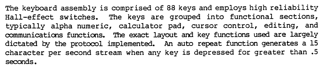
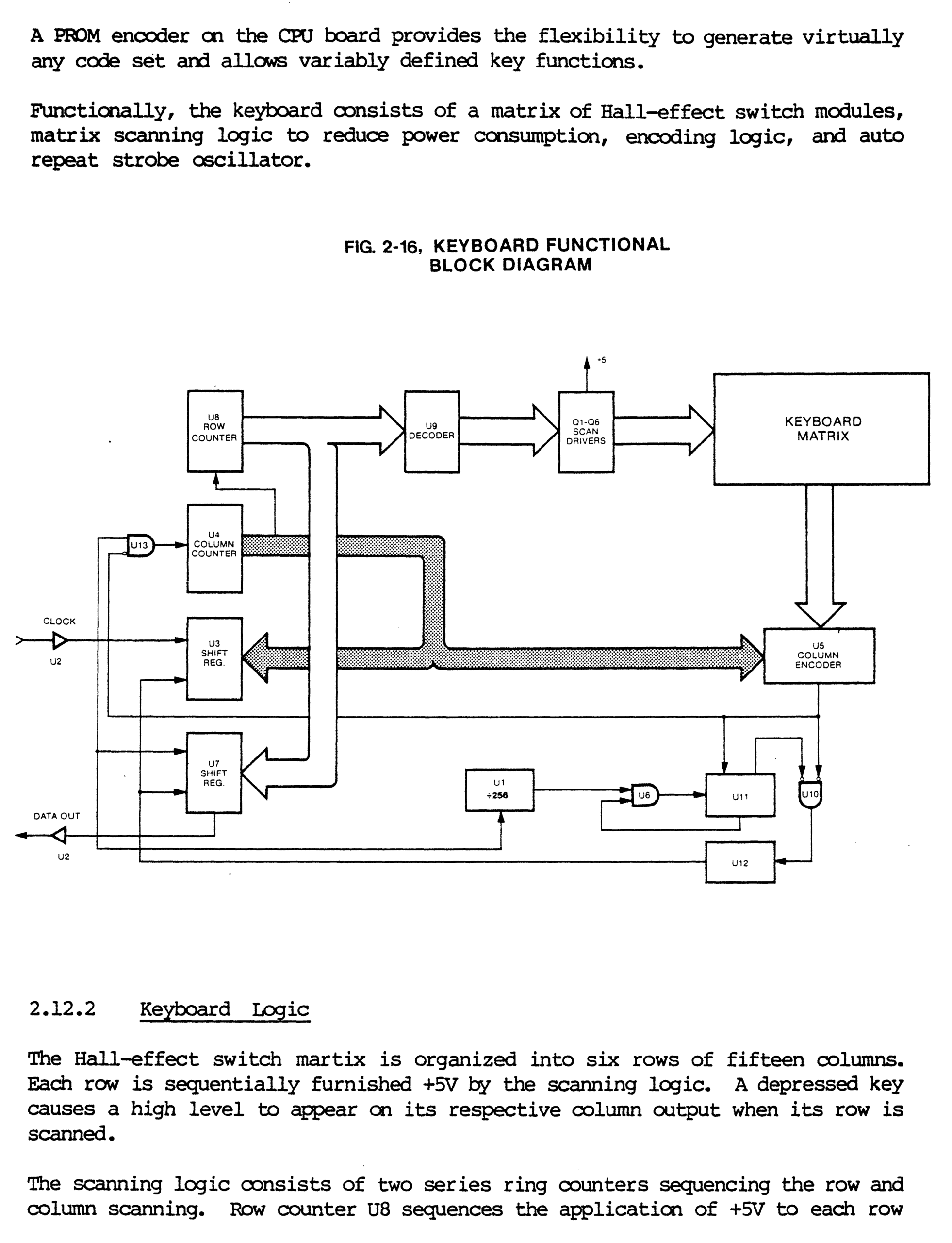
The technical manual gave me some clues:
The keyboard clock was about 75kHz.
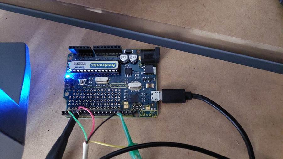
I wrote some keyboard code for Arduino Uno. It needs direct port reads and writes to be fast enough. I worked out pinout for the keyboard connector and made up cable to the Uno.
Initially I had no joy at all, but found a broken pin on the interconnect between the board and the I/O module used for the keyboard. This deceived me with the pinout – I had 5V and the data input reversed – lucky there was a current limiting resistor. Once fixed, the keyboard recognised when a key was hit but made no sense of the data.
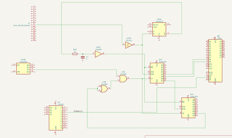
The data seemed to be making it to the shift registers, but the control of the shift registers looks a bit random. There is a monostable involved. Perhaps a dead tantalum. I’ve had a few lately. Back to buzzing out circuits.
This is roughly what I found:
It’s not 100% accurate – I used a 2716 instead of the 2708 just because the symbol was already there, and I’m lazy.
The start bit triggers the monostable and, once it works its way through the registers, it disables the clock.
The monostable times out after about 250ms when it clears the shift registers which re-enables the clock. I found some glitches at the input to U50C which became pulses at the output and prematurely cleared the shift registers. I don’t know why the little filter is there, but it gives an opportunity for noise as much as it removes it. I halved the resistance and the problem went away.
The ROM is small but quite large for character mapping – 1024 possible inputs and 256 possible outputs. When the clock stops, 16 bits are captured in the shift registers. The first one is the start bit. The next 10 feed the EPROM. The last 5 may not be used at all, but could be used eg for a hard reset.
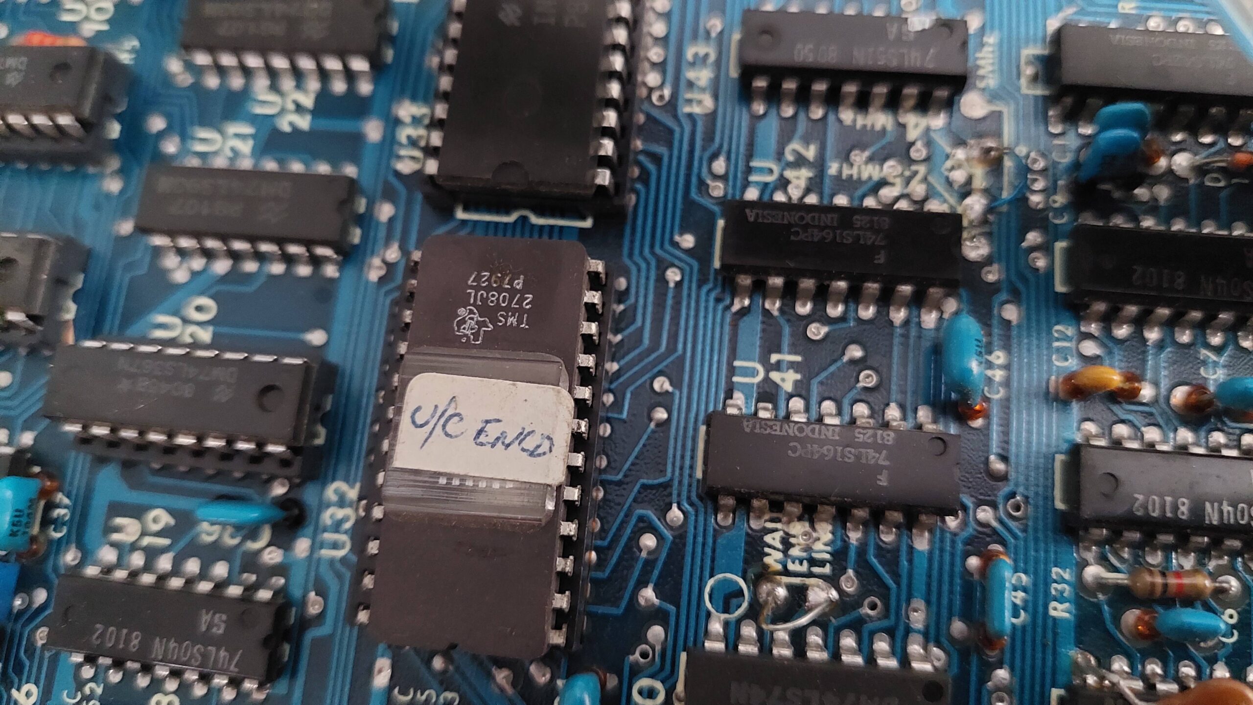
The manual suggests the scan codes are converted to ASCII. I needed to feed in the unknown scan codes. Being a 2708 i could not read the EPROM with my programmers (i can now). I had to catch up with Andrew P at the ARC to borrow his EPROM reader.
I was impatient though so I attempted to work it out.
There are a lot of codes to enter, and the system doesn’t respond to many of them. Often, it gives the same response to several codes. Sometimes the response is one-way and requires a power cycle. The manuals give some clues but not enough.
Curiously there is a monitor command that goes into a terminal mode where everything goes out the serial port. I had already discovered that depending on when I entered this character I sometimes got a “t” or the screen cleared and machine hung – this is the terminal mode!
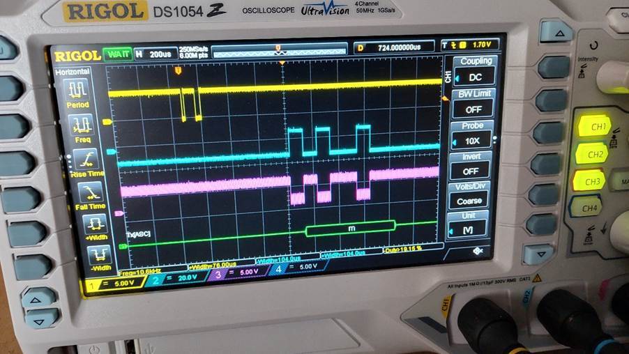
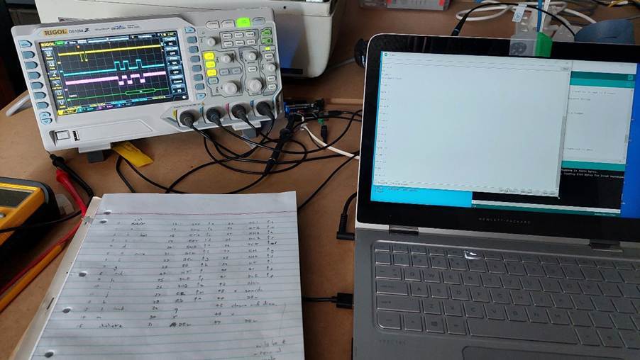
I connected an oscilloscope and used its RS232 decoder to check the ascii characters. The port requires a null modem to transmit. It worked fine.
This was a much better way of seeing what was generated for each code, but there were still several codes generating the same ascii characters or the same ascii characters with the eighth bit set.
I used the first code that created a character to make a map which I added to the Arduino code. It’s kludgy to use the Arduino serial monitor, but it seemed to check out ok. It was good enough to try to boot the machine.