I feel like a computer is incomplete without a serial line, so i procured a HP82939A Serial Interface. It requires the I/O ROM for operation.
The serial properties are set by DIP switches inside the package, so it’s a screwdriver job. I used 2400 baud, 8 bits, 1 stop bit, no parity.
Then I set this back to defaults to appease the terminal program which insisted on factory defaults: 7 data bits, 1 stop, 300baud.
I left the plotter at the original settings, so the initialisation program needs to program the serial port via CONTROL statements. (See I/O ROM Manual)
The device number is 10 which is the default.
It worked fine with the plotter.
The Data Communications Pac includes a terminal program, TERMEM. The comms parameters can be changed via the soft keys.
Generously given to me by Michael from the ARC Group.
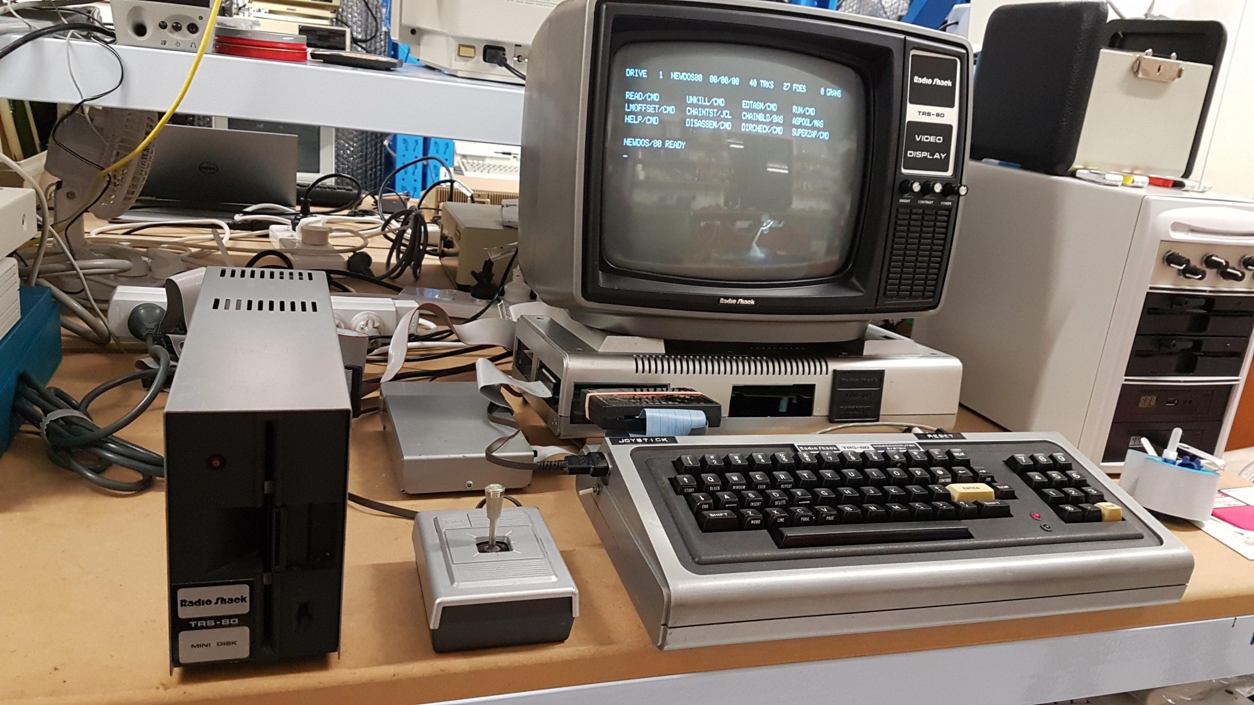
The Model I was originally released in 1977, but this one was made in about 1980. It has 16k of memory and has been highly modified.
It also came with an expansion unit with RS232 interface and 32k of additional memory. There was no disk drive, but that was only a minor obstacle.
It also came with an original monitor (probably not the ideal one to use with the expansion box), buffered cable to connect the computer to the expansion unit, a box which turned out to be a high resolution graphics mod, a joystick, and dust covers.
Inspection didn’t show any particular problems. The power supplies are quite simple and don’t seem to have any of the usual EMI filtering.
Everything fired up without smoke. The rails looked clean, and I adjusted the supplies on both the computer and the expansion unit.
There are a lot of modifications including:
High resolution graphics
Lower case mod
High speed mod
Joystick
Termination of control signals on the expansion unit
Cassette modification
Reset switch
This machine was obviously owned by an enthusiast.
I only briefly got clear text on the monitor, and then it would not sync. This was traced to Z5 in the sync generator, which is a common failure point. This is a CMOS part and I replaced it with an 74HC02.
Some keys were generating strange character sequences. This was caused by a broken wire ground on the keyboard cable which was somewhat fragile.
The machine uses an ALPS keyboard and the key switches seem to be working well.
I replaced the keyboard cable using the instructions here:
I found the keyboard ic positions too close to the connector so I had to bend the pins up at 45°. I also added some earth lines to try to provide some shielding. The keyboard is mounted using some rubber mounts which had deteriorated. I replaced them with rubber tubing.
The amount of RAM reported by the ROM basic (PRINT MEM) was variable. I had four spare 16k RAM chips, so I kept on swapping the mainboard RAM chips until I got the full 15572. Then I repeated the exercise on the expansion interface. I found 5 dubious RAM chips which were replaced.
Expansion Interface 48k top
FFFF
-1
Expansion Interface 48k bottom
C000
-16384
Expansion Interface 32k top
BFFF
-16385
Expansion Interface 32k bottom
8000
-32768
16k top
7FFF
32767
16k bottom
4000
16384
3FFF
16383
0000
0
The screen showed artefacts on the two bottom lines and occasionally on the two lines above. These changed as new text was displayed over them but the text was incorrect. Looking at the text it was apparent that the LSB was always set.
This becomes very annoying because the bottom lines are copied up as the text scrolls. Eventually the whole screen is filled with corrupt text. For now, I can keep clearing the screen, but it needs to be fixed. This was due to a faulty video RAM chip 2102 at Z48. It was replaced.
With this last fix the machine appeared to be working.
The machine came with a high-resolution add-on / modification by Microware Computing Services. It seems to be an unusual thing and is probably of limited use but is interesting nevertheless.
The Model I in its base form allocates 6 bits for each character on its 64 x 16 character display. Each character consists of 6 x 12 pixels. In text mode each character is translated from its 6 bit representation to a 6×12 pixel “picture” by a PROM. The PROM (according to legend) supports 128 characters including lower case letters. A common mod adds one more video ram chip to allow access to the other 64 characters.
The video RAM is 8 bits wide (with no bit 6) with bit 7 indicating that the character is graphic character. Each of the 6 bits can be used to turn on or off one of 6 graphic cells each of which is 2×3 pixels ie half the width and one third the height of a character. This gives “low resolution graphics”.
The high resolution mod drops into the socket for original PROM. It includes an EPROM that fulfils the role of the PROM when the high resolution mode is off. When the high resolution mode is on the mod takes over.
Physically, the mod consists of a box which hangs off the expansion port, a small daughterboard that sits in the main unit. The daughterboard plugs into the original ROM socket.
The mod includes 2k of RAM which is used to store 16 bytes for each of 128 graphics characters. Only 6 bits are used (characters are 6 pixels wide) and only 12 bytes are used (characters are 12 pixels high). Note – this is not video RAM – its is more like the original PROM but writeable.
The RAM is accessed via the expansion bus. It is mapped over the system ROM so it is write-only memory which makes it a little hard to test.
The RAM is dual ported and a register in I/O space (accessed via the expansion interface) is used to control whether data is read by the graphics generator or written to as memory.
The bottom 3 bits of the I/O address are don’t cares.
OUT 130, 1 -> Character data read by graphics generator

OUT 140, 1 -> Character data writeable starting at #0000
A second register in I/O space is used to select between the standard text/graphics or the high resolution graphics.
OUT 150, 1 -> Use the default text/graphics (holds the high res graphics shift register in reset)

OUT 155,1 -> Use high resolution graphics (holds the text and standard graphics registers in reset)
There are demonstration disks show how the graphics work.
Boot up on the demo disk
Load basic. Hit return at “number of files” and 60000 at “memory”.
The machine included a modification that allowed either the original clock (1.7MHz) or a slightly faster clock (2.6MHz) to be routed to the processor. The high speed was enabled at power-up, although that seemed to be a matter of luck as there was no reset on the register. I’ve added a system reset so that it defaults to the normal speed. I suspect that this might be more reliable.
The mod includes a register in I/O space to enable / disable the high speed clock.
OUT 254, 1 --> Changes to the high speed clock

OUT 254, 0 --> Changes to the normal clock
The mod includes a LED to indicate whether “turbo” mode is activated. I’ve added a series connector so that the lid can be separated.
The joystick mod was incomplete – there are some cut wires and an unused DPDT switch nearby that is unused. It’s possible that the mod was completed or stopped working and was disabled.
Commonly, a joystick was added by using the switches to tug down on D[4:0] using the joystick switches. Apparently, sometimes this wasn’t even gated with an address, but it looks like this mod had some address decoding.
Reverse engineering it shows three signals ANDed together. One of these would have been IN_L and the other two would have been address lines (both 0). This doesn’t fully decode the I/O space but does restrict it to a quarter of the space. This at least gets it away from the cassette interface and the high-res graphics at 255 and 254.
I found an instruction sheet for the “Alpha” joystick. It has the same data line assignments as the mod:
D0 UP

D1 DOWN

D2 LEFT

D3 RIGHT

D4 FIRE
The instructions indicate the address is 0 which is again consistent.
It notes that some games expect FIRE to be indicated by D0 and D1 being low simultaneously (STICK-80 vs TRISSTICK). I expect that the toggle switch was used to configure the interface accordingly.
I wired it all up. Being something of a tangled mess of flying leads makes it very easy to break wires, so I’ve added an inline connector.
I used the alpha test program:
Alas – no joy. The scope showed that there was no IN strobe and this was because of a dwarf pulse at Z23-8 (74LS32). I replaced the IC and it came good.
I have not tested this yet. An additional character RAM has been added at Z46. The machine seems really designed to have this IC because the modification seems quite simple. This is covered by Technical bulletin I:35.
The lower case version of scripsit “SCRIPSIT/LC” demonstrates it.
The reset switch just parallels the existing reset switch. I added a series connector so that the lid could be separated.
Top cover connections
The mods add an LED (turbo), reset button, and joystick mod. This makes it impossible to remove the cover from the main board. I’ve added in-line connectors so it can be detached.
The system did not come with a floppy disk drive. I did my set-to work using a Dick Smith drive from my System 80 and my generic drive unit.
Ben G from the Australian Vintage Computer Collectors had a genuine one, though, which he passed on at very reasonable cost (not the first time he’s helped me out).
I made up a new cable, as I’d been using the System 80 cable. The Tandy cables used connector pin removal to set the drive numbers – all the selects are connected inside the drives. I really need to pull some pins from the connector but for the short term I taped over DS1 (p12), DS2 (P14), and DS3 (p32) leaving just DS0 (p10) on the drive connector for the Tandy floppy drive.
As is often the case with 40-year-old drives, it did not immediately work. I did the usual clean up, lubrication, and alignment (using Imagedisk) but it had a peculiar issue of losing half the head steps. This turned out to be a timing problem with two monostables that control the stepper motor. One had an adjustment pot, but I had to change the resistor on the other one.
Apparently i couldn’t find a schematic.
Once the timing issue was resolved, the drive could be aligned. Adjustment is by loosening the motor screws and rotating the motor body, but it didn’t have enough play, so i had to move the shaft coupling a little as well.
I found the cable unreliable and after several frustrating hours of checking and rechecking I found that the floppy drive connector on the expansion box had been ever so slightly modified. One side had been filed down – presumably to accommodate a tight floppy cable connector.
The connectors I used on my new cable were just a little wider, so it was possible to be out by half to one pin, resulting in shorts/opens. I need to build up the connector again, but it works fine as long as you know and position correctly!
Why “jmp start ;microcomputers”? Well, ultimately it’s just a name. It sounds like “jump start”, but it’s also a pretty common line of assembly language. It’s a bit technical, but so is this site. I tried some AI names, but this came out of my head.
A microcomputer is a computer that is based on a microprocessor; a highly integrated processing unit that first appeared in the early 1970s. The term “microcomputer” was used a lot during this early adoption period but fell out of fashion by the early 1990s. Microcomputers are now referred to as PCs, notebooks, tablets, phones etc, so i use the term “microcomputer” as a shorthand for “vintage microcomputers” which are the subject of this site.
As i emerged from high school in the early eighties, microcomputers were the tech that everyone wanted, and this prompted me to enter the world of electronics. I got to play with several early machines, but there were so many that it was impossible to experience the gamut.
Over the last 8 years, i’ve had the opportunity to not just reacquaint myself with some familiar machines, including a couple i sequestered from those times, but also to experience many that i missed the first time around.
I’ve purchased many of my treasures through well known online marketplaces, but i have also acquired many from colleagues at the Adelaide Retro Computing Group – always at reasonable cost and often as generous gifts. I’ve tried to acknowledge significant gifts as i’ve added detail, but i apologise in advance if i have missed anyone.
I’m typically interested in workhorse machines but use the occasional game to demonstrate what a computer can do, or in many cases its limitations.
Making machines shine figuratively is my goal, including:
Getting them working
Getting them working again after they stop
Adding software
Adding accessories
Connecting them
My machines are not pristine or mint – i aim for tidy and functional. I like them to be exercised regularly and standing by, ready to save mankind when the current tech collapses in upon itself like an abused CRT.
Generally i will try to make sure that machines are either original or can be readily taken back to original – and that includes modifications from, or typical of, the operating period.
I do compromise on hard disks; they are difficult to source and inherently unreliable. I never bin them, but i don’t think twice about replacing them with hard disk emulators. I also use disk emulators alongside original storage peripherals to make it easier to try, and to demonstrate, a greater range of software.
The purpose of this site is to:
Show off some of my machines
Make what i’ve learnt available to others
Promote related local activities and groups
The info that i’m posting has been extracted from the notes that i have accumulated since 2017. Those notes were pretty rough and not always complete. Mostly i’ve rewritten them here, but their heritage still comes through in places.
My hobby relies on the amazing work that has been done by so many people to archive data – programs, disk images, data sheets, schematics, manuals, articles, photos, problems and solutions. I use these resources extensively, and i am grateful for them. I try to pay this forward by archiving disks and documentation to archive.org or other appropriate sites such as Microbee Technology.