Having demonstrated that it is possible to build a system using the 6016 and 6080 cards it was time to set up a more robust system.
I had a very large enclosure setup including the drive and an Adaptec SCSI interface card. It has a rear panel that supports lots of D connectors.
Although having 10 slave processor cards is overkill it would certainly demonstrate the capability of TurboDOS. None of the pulsar cages seemed to have the current capacity required for that many cards, but there was a spare Pro-Log cage that looked suitably robust.
The enclosure was designed for an 8” drive and the distribution disks are 8”. I had an unallocated NEC 8” drive from about the right period.
The power budget is as follows:
Device
+5V
+12V
-12V
+24V
Master 6016
3
0.1
0.1
10xSlave 6080
20
6 (I’d be surprised if it’s this high.)
1
Floppy Disk Drive
0.9
0.9
Hard Disk (est)
1
1.5
Fans
0.5
Total
25
7.6
2
1
Used
40
10
10
5 (will replace with 3)
I used 4 separate supplies which complicated the mains wiring a little but matched the loads. The -12V supply is the same as the +12V but wired for -12V. The fans run off it to provide a minimum load.
The main switch was originally a key switch, but without a key it needed to be replaced.
Any mains wiring that could come into contact with low voltage wiring was sleeved.
The card cage already had a power connector and loom so it just needed reterminating.
Layout was a compromise. The supplies had to be mounted with the terminal blocks accessed from within. The 8” drive pushed the cage back as far as it would go while allowing access to the power supply terminals.
Three fans were included – one to cool the power supplies and the other to cool the processor cards. The case lid was modified to allow for the fan inlets.
Note to self: I wonder if that poorly mounted crystal accounts for keystrokes not being seen by the seventh card (The order changed a bit).
I had two unallocated NEC FD1165 8″ Floppy Disk Drives. This is a half height unit that uses 24V for the spindle motor.
The heads on this unit are easy to access once the drive cover is removed. Annoyingly, the configuration links are on the reverse side.
This unit, in its standard configuration, refused to release the door latch which was a little inconvenient. I changed a solder link so that it was more willing – “in use”.
Section 2.8 of the maintenance manual:
Function
Label
Position
Setting
Drive Identification
DX
1
Device select 1 (first device select) – Drive A:
Head Load
HL
2
Head loads with device select
Radial Ready Jumper
RX
1
Ready Gated by Drive Select
Side Select Jumper
SS
1
Use side select signal
Write Protect Jumper
PR
1
Send write protect and enforces write protect
Door Lock
DL
2
HL.DSX + DLH DLH= Door Lock Hold
DR
2
DH
2
In Use (Solder)
IU
2
Read Data
RD
1
Enable read data
Busy Lamp Indicators
BU
1
BS
2
Weird setup!
T1
Installed
Prevent rapid head load/unload
One of the two drives (let’s call it drive one) had been dropped at some point in its life. There are some significant dents in the chassis and the top head was initially at an unexpected angle.
I repaired this when I was imaging the 8” disk collection, and the drive operated quite well during that exercise.
The second floppy disk drive was not reliable when I had previously attempted to use it but i had not investigated further.
I used the first unit to create system disks and these disks worked well.
While loading software on to the hard disk using the first unit, I noticed that some disks which had been successfully imaged with unit one were not being read by the system using the same unit one. Of course, the processing done by the greaseweazle is quite different from that done by a real floppy disk drive controller, so the performance is not necessarily the same.
I imaged my configured boot disk using greaseweazle with unit one. Drive two was swapped into the system. It did not work with the original disk or with a new disk written by drive one.
Drive two did boot if i wrote the disk using drive two. This suggested that the alignment of the two drives was different.
The second drive was able to read some of the disks that the first drive could not, but not all.
What followed was several days of frustration, which left me with the impression that these drives (in combination with the floppy disk controller and ancient floppy disks) are not quite at the peak of their performance.
I initially used just ImageDisk to align the drives. This is a little tricky because I have no reliable double-sided reference disks. I do have a reliable single sided reference disk. For the second side I checked alignment using disks that had been written back in the golden age when the writing drive was in its prime. I checked with several disks which may or may not have been written with different drives!
The drives were not optimum. I’m sure I aligned the first drive prior to imaging, but its possible the alignment has shifted (my shed temperature has dropped significantly). I adjusted the drives as best I could. Using the Microsoft Multiplan disk, the drives seemed solid from track 0 to track 76.
Changing to some other disks (with a smaller number of sectors) the performance seemed less consistent with marked variation between tracks. Adjusting the bottom head involves moving the stepper motor baseplate – three screws loosened and then using a screwdriver to muscle the baseplate in or out, noting that the tracks have about a 0.5mm spacing. Often drives have a mechanism that convert quite large adjustment to effect a small change in position. Not this one. It requires a very gentle touch to get it in the optimum position.
As for most drives, the top head is adjusted relative to the bottom head. It requires even more patience because it is mounted using two screws which, once released, allow a lot of movement over a 3mm x 3mm plane and a wide range of angles. Extreme patience is required. The maintenance manual doesn’t even describe this operation – recommending replacement of the carriage instead. Nevertheless, it is possible to manoeuvre the head into a good position. Both drives required adjustment.
Unfortunately, the PC disk controller was too sensitive (two easily satisfied), so i could not get the alignment quite right for the actual system, which is fussy. I still had trouble reading original disks.
I then turned to instrumentation. I used the test points (8/9) and an oscilloscope in differential mode to get some additional info – the magnitude of the signal. This is at the output of what may be a custom amplifier. As was clear during the imaging of the 8” disk collection, performance declines with track number. The signal to noise ratio is significantly worse on the inner tracks, even when optimum. It was also clear that the magnitude was not steady.
I also happened to have an SA 120 alignment disk, which is very good for aligning the bottom head, but not the top head. It’s single sided!
The test signal is at Track 38. 100mV/div. 20ms/div. It is the gold standard, but may be less than optimum for the disks if they have been written out of alignment. There may also be a better compromise position if the top head is just a little out.
The whole concept of reducing the write current on, what are smaller sectors, seems to be a solution fraught with peril. Maybe they should have stopped at 60 tracks. I’ve noticed repeatedly that failures are likely on these inner tracks.
Having used this method the second drive was pretty good but the first drive is still unreliable.
Along the way I found a few things:
When I configured the boot disk I added the card boot files to a disk that was close to full, so they got written to the inner tracks.
I found that on occasions the boot process gave up on the floppy disk and went looking for the files on other drives eg the scsi2sd drive. This eventually led me to find that the floppy disk only needs to contain osload.com. No boot tracks are required. Osload is happy to load the card boot files from E:, after which E: becomes the system disks. For whatever the reason, the ROM can find Osload on the floppy but not on the scsi2sd.
If the drive is configured as drive 2 (second device select) it still boots but the drive is B:.
I had one more try at the first drive. I spent a lot of time making sure that the alignment gave the same amplitude for both heads. I checked it with a disk written by the second drive. It was not identical, but it was pretty good. But still it would not boot from disks written by the other drive.
In desperation, I thought I would just try aligning the bottom head (and hopefully the top head with it) by nudging and trying to boot. Eventually a found the correct position. It was not a big change but it was definitely different from where I had it. So, in a boil over, the correct position is not where the maximum amplitude is – unless, of course, something moved.
I noticed discrepancies between the two drives, so I tried a new alignment technique. Noting that problems are exaggerated on the inner tracks, I used greaseweazle to read just the inner tracks. The Disks were written with the second drive and read back with the first drive. By adjusting the carriage alignment in very small steps and then reading back it was possible to improve the alignment until bad sectors were not read.
This proved to be quite effective. Although the alignment was good, it is simply the case that the first drive does not read as well as the first. One disk would not boot on the first drive, but would on the second. Reading with greaseweazle with either drive was fine – even with only one rev. Once the disk was written with the first drive it would boot on either.
Along the way I noticed that the floppy disk controller card offers some options wrt precompensation. There are some links on the card. I have no idea whether the settings are correct for the drive. No doco. No mention of precompensation in the drive manual.
I think I now have two drives that a reasonably aligned. I have loaded a lot of software off a variety of disks using the second drive. No doubt the alignment of the two is imperfect. The second drive seems to perform better – perhaps it is better aligned, but I think its read circuit just performs a little better.
Greaseweazle/HxC perform better than the physical drive controller. I guess that’s the advantage of processing power and the ability to post-process but i have had the converse as well eg the Sorcerer with the Micropolis controller.
HP called the HP-85 a calculator, but it was definitely a microcomputer. It runs an HP designed Capricorn microprocessor at a seemingly slow 613kHz, but with native floating point operations it was excellent for scientific calculations.
Having had an HP-11C since my uni days, i have a soft spot for HP gear. The computer itself was a quite a modest ebay purchase in about 2017, but i was aware when i bought it that it may be quite a project.
It sucked me right in. There’s a lot of love out there for this machine and its brethren. Curious Marc has done as much as anyone to raise interest in this machine. There is a ton of data available from the HP Museum and more at the HP Series 80 website. There is also an email group. I found myself wanting to get the most out of it.
I replaced the tape drive capstan rubber and modified the capstan to accommodate QIC tapes, which are easier to find than the original DC100 tapes.
At the back of the unit is an expansion bus that can accommodate I/O, RAM, and a ROM tray. I added 16k RAM, HPIB, Serial, and PRM-85 ROM boards. The PRM-85 mimics as many ROMs as i could have ever needed to poke into a ROM tray.
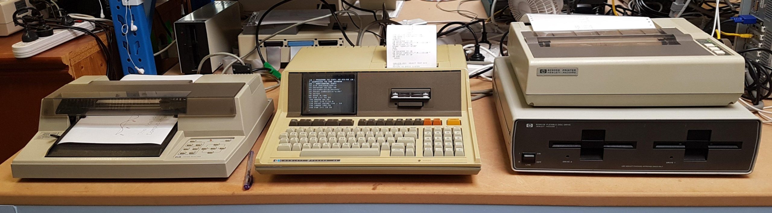
I added an HP-IB printer and a serial plotter (recently a friend found the HP-IB version for me – thanks Mike). I asked if anyone on the Australian Vintage Computers FB page might happen to have a drive unit – sure enough, Ben just happened to have one at very reasonable cost. I really appreciate the help that people give me to get things going.
The icing on the cake was when another group member offered me a box of DC100 tapes. Thanks, Chris. I’m in the process of refurbishing them with new drive bands. Maybe i will be able to revert the tape drive.
These days, an EBKTS board is the go-to for these machines. It’s a brilliant solution to either get started or just to experience everything the machine offers without the hassle of quite complex repairs or tracking down hard-to-get expansion modules and peripherals. It serves up disks and tapes from solid state storage.
The EBKTS wasn’t available when i started, so i was forced to do some hard yards. I don’t regret that; the tape and floppy drives add a lot of character. I will get an EBKTS at some stage, but the aussie dollar is pretty awful at the moment.
The machine was plug and play – apart from the well documented issues with the tape drive. The capstan rubber turns to mush and can easily destroy a tape.
Destroying tapes was not an immediate issue for me, as i had none. It would soon become an issue, though, because tapes were the only means available to me at the time to load and save programs.
On power up, the machine displays a cursor for the basic interpreter. It is happy to immediately evaluate an expression and display the result.
The cursor can be moved around the screen to edit and reuse text. The screen rolls up and down, displaying 16 of 64 stored lines. This makes it pretty easy to use the small screen.
Basic programs are entered in the normal way. Data can be printed to the screen or to the thermal printer.
Inside, the machine is a joy to behold, with lots of ceramic packaged ICs and a neat arrangement of the CRT, thermal printer and tape drive. Outside, the case is quite yellow, but brightening cases is low on my to-do list.
Browsing the web quickly revealed that DC100 tapes were scarce and unreliable, and it was widely recommended that the tape drive be modified to accept QIC tapes, which are not as ancient and a lot easier to procure. I placed an order for tapes and set about attempting both the necessary mods and the capstan repair.
The tape drive mod is described in detail here. It requires a change in one resistor to account for the slightly different magnetic properties of the tape. This was easy.
The mod also required the wheel to grow a little to account for the slightly different dimensions of the cartridge. This was hard. The last thing i wanted to do was to put the existing capstan in the hands of a tradesman because i feared for the rotary encoder.
Instead, i crafted a piece of plastic to glue to the top of the capstan. After a few tries, i got it to bond. I use the drive sparingly (i now have better alternatives), but the extension is still there many years later.
I worked through several versions of rubber replacement and eventually i had success with 6/9mm surgical rubber tubing.
Reliability is not great but, it is good enough to demonstrate operation. QIC tapes are tight in the drive slot, which makes them a little tricky to insert. I found that if i kept the front screws of the enclosure a little loose, it was easier to insert. Not great but acceptable. The alternative is probably a file.
Of course, once you have a tape drive and some viable tapes, there is the small matter of getting software on to the tapes.
The HP-85 tape drive was never going to be a daily drive proposition and the HPDrive emulator, good as it is, is a bit unwieldy for a convincing demonstration. I really needed (wanted?) a disk drive.
I kept an eye out for a disk unit. They are usually very expensive and i’ve only seen them listed for sale in the states, from where the cost of postage is horrendous. I did find a cheap 3.5” unit, but the thought of paying nearly $200 for postage prompted me to scream for help on one of the facebook groups.
To my surprise a gentleman Ben G happened to have a M82901 Dual Drive uniit out in a container at his property in NSW. He was kind enough to send some pics, explain the unit’s shortcomings, offer it at nominal cost, and arrange for its dispatch. That was a generous thing to do.
When it arrived it was clear from some dents and gouges that it had landed very heavily at some stage. Ben said that he’d recovered it from a gold recycler.
There were rattles in the box and once opened some damage was apparent. Both of the drives had parts of the plastic broken. The interface card was only secured by a couple screws used to secure the circuit card on the right drive. Not a great effort from HP really but I guess they weren’t planning on the unit being thrown on the scrap heap.
I attempted to glue things up but it will always be fragile. I pulled it all apart, cleaned it up, checked the supplies and put it all back together.
The drives are PC style double height double sided units. The heads were not moving easily so they needed some lubrication and bit more rough treatment to get them moving again. Once they were free, i connected them to a PC for alignment using ImageDisk.
One was pretty good on the PC but the other had some issues formatting; successful but with lots of retries so I subbed in a known good spare drive.
There’s a set of dip switches that set the HP-IB address. The drives are referenced by “:D720” where the second digit is the HP-IB address and the third is the disk drive number.
Format with:
INITIALIZE “<label>”,”:D720”
The drive unit failed to communicate.
Fortunately, the manual was available online and the unit has built in self tests. It took a while to work out how the tests worked and they seemed to produce very erratic results. It seemed to consistently show that the RAM test was failing so I ordered some new RAM. 128 byte static RAMs.
I also read back the ROMS using an EPROM programmer and that suggested that one ROM didn’t seem to be working. I scrambled to see if the binaries were online. Fortunately there were.
The natural replacement would be 2716 EPROMS but I only had 2732 EPROMs. They have a compatible footprint but with the upper half being the active portion. My EPROM and cheap EPROM programmer did not play nicely together but eventually i convinced myself that i had two working EPROMs.
After spending a long time searching for a problem which turned out to be incorrect configuration, i was able to get all of the tests to pass with a known good drive. That meant the controller was good. Even better the unit worked with the HP-85!!
Neither of the two original drives wanted to play the game. I had a good look at the writes on the first drive. Everything looked good except the signal on the top head was different to the bottom – about half the size. That made me have a closer look at the head which I discovered had been damaged – it looked like a piece of ferrite was missing.
The other drive’s heads seemed ok, and I’d checked the first drive’s electronics pretty thoroughly, so I thought I might get a second drive working by swapping the electronics card. That worked.
Sure enough the HP 85 could happily operate two drives.
The other original drive now has an electronics fault as well as a drive head fault!
I needed some disks to try it all out. The teledisk images I had seemed to often be for 3.5” drives and wouldn’t write to 5.25” disks. Instead i used the HPdrive emulator and copied them across:
COPY “:D700” to “:D720”
It’s not fast.
I found many of the disks would not run unless labelled correctly. The failing line of basic revealed the required label.
I spotted an HP 82905 printer on ebay. It was made by Epson. I’d never seen an HP-IB printer come up before, so I grabbed it. I figured that it would be cheaper to run than the thermal printer. I was hoping that it might be good for Centronics as well, but not so.
It needs the Plotter/Printer ROM, which I was surprised to find was not on my PRM-85 super ROM. See the post on the PRM-85.
The printer can be set to be the default printer:
PRINTER IS 701,80
where 7=GPIB and 01=GPIB address – set with DIP switches under secret panel on top of the printer.
I punched in the screen plotting program in Application Note: Copying CRT Graphics from the HP-83/85 to the 82905B.
The HP-85 comes with a Tape Drive, a Thermal Printer, a CRT display, 16k of RAM, and Basic in ROM. Out of the box, there is no external I/O, but it does have a 4 slot expansion bus that can accept modules, of which there are many.
The expansion bus not only allows additional I/O to be added but also additional RAM and ROM. Probably the most important I/O to be added is a HP-IB interface to support connection to many peripherals and instruments.
The addition of ROMs allowed command set enhancements and in many cases the use of additional I/O or peripherals needed enhanced commands. eg the use of disk drives requires the addition of a mass storage ROM and an enhanced mass storage ROM. A plotter requires the addition of a Plotter/Printer ROM.
ROMs were sold individually and were plugged into a ROM tray that plugged into the expansion bus.
The exercise of finding the individual ROMs and the ROM tray requires deep pockets and patience. Noting that providing code in ROMs is fairly easy to do, it was a matter of time before an alternative solution appeared.
The HP computer community is awesome and some years ago a couple of gents (Bill Kotaska with support from John Shadbolt) developed an expansion module, PRM-85, that emulates a ROM tray.
I had gathered an HP-IB and serial cards, and I had a serial plotter and an HP-IB printer. I also wanted to be able to use HPDrive to emulate disk drives via the HP-IB interface, including SS/80 protocol. To achieve this, i needed the following ROMs:
EDISK (85B version – supports Extended Mass Storage
Mass Storage (85B version) – supports Extended Mass Storage
Extended Mass Storage – Supports SS/80 protocols
Input/Output – Supports HP-IB and Serial interfaces
Plotter/Printer – Supports plotter peripherals
All the ROMs have been captured and can be loaded into the onboard ROM. I contacted Bill in 2018. They had done a small run the previous year and had one left, which I purchased for much less than the combined cost of the original tray and ROMs. The details are here. ROM info is here.
The “85A without EMS” uses the first ROM socket on the PRM-85. It uses the 8 predefined addresses below:
Jumper J10 Decoded
Contact#   ROM Address  ROM Name
---------- ------------ --------------------
  17       232 (E8 Hex) Advanced Programming
  18        40 (28 Hex) Assembler
  19       224 (E0 Hex) Service-85
  20         8 (08 Hex) Program Development
  21       208 (D0 Hex) Mass Storage
  22       176 (B0 Hex) Matrix
  23       192 (C0 Hex) Input/Output
  24       207 (CF Hex) Extended Mass Storage
But for the 85 to use SS/80 disk storage requires the “85A with EMS” Super ROM. This Super ROM replaces the Program Development ROM (08H) with the 85B EDISK ROM (D1H) and the Mass Storage (D0H) with the 85B Mass Storage ROM (also D0H). The address D1H requires DIP Switch 1 as it is not one of the predefined addresses.
Jumper J6/9/10 J6=1-8, J9=9-16, J10=17-24
Contacts  ROM Name
--------  ---------------------
 9 to 17  232 (E8 Hex) Advanced Programming
10 to 18  40 (28 Hex) Assembler
11 to 19  224 (E0 Hex) Service-85
 4 to 12  209 (D1 Hex) EDISK (85B version) - set address with first DIP Switch
13 to 21  208 (D0 Hex) Mass Storage (85B version)
14 to 22  176 (B0 Hex) Matrix
15 to 23  192 (C0 Hex) Input/Output
16 to 24  207 (CF Hex) Extended Mass Storage
The second ROM slot on the PRM-85 is available. It can take up to a 27C512 for 8 x 8k slots. I had a 27C256 so that was 4 slots. Practically, though, the only addresses left were the predefined 08H and the second DIP switch.
I could add the Plotter ROM (F0H) using the DIP switch and pop the Program Development ROM (08H) in next to it.
Jumper J7/8 J7=1-8, J8=9-16
Contacts        ROM Name
--------        ---------------------
4  to 20(J10!!) 8 (08 Hex) Program Development
5  to 13(J8)    240 (F0H)  Plotter/Printer  - set address with second DIP switch
I think i could probably add a couple more ROMs to the second EPROM. They could not be used at the same time as the Plotter/Printer ROM. The link from J7-5 to J8-13 would need to be changed and the second DIP switch changed to the appropriate address.
ROM Name               Number Switch settings
---------------------- ------ ---------------
Advanced Programming 2  231   11100111
Matrix 2                177   10110001
Plotter/Printer         240   11110000
Having a computer that can write and read tapes is great but, that left the problem of getting software on to the tapes.
The HP-85 doesn’t have a lot of I/O built-in but, it does have 4 expansion slots that can accommodate various adapters such as HP-IB (GP-IB), serial port, and a ROM tray for expansion ROMs.
The most popular technique for file transfer is to connect a disk drive to the HP-IB adapter. I also considered using the serial port but, I wasn’t sure that it would work.
So I needed HP-IB adapter. And, of course, to get a HP-IB adapter to work with a disk drive requires some expansion ROMs. Actually, if it had been an HP 85B instead of an HP 85, they would have been built in. It wasn’t though.
That meant I needed an HP-IB adapter, a ROM tray, and the various ROMs. None of this stuff is easy to come by. I did find a few vendors in the US with most of the items – unfortunately at high cost, high postage, and low interest in going to any trouble. This led me to the PRM-85. See my separate post on this.
I found a GPIB card in Australia on ebay, so I grabbed it.
There are not many computers that use HP-IB for their disk interface (the Commodore PET is one) so only an HP drive unit will do, and they are even rarer than DC100 tapes.
The HP computer community is awesome, though. Recognising that HP drives were becoming very rare, a chap from the HP 9845 project set about creating an emulator called HPDrive.
It runs on a PC with a GP-IB adapter installed, and it is particularly good. I followed the instructions at:
GP-IB cards are generally expensive but, fittingly for such a project, I found a reasonably priced National Instruments ISA card that seemed suitable (suitability is described in detail at the project site).
Then of course I needed a computer with an ISA slot. I had an old Windows 2000 machine stored in pieces that had a slot (I had some other older options as well) so I set that up with the downloaded disk images. I’m never short of a project.
And it just worked. To get the disk catalogue type:
CAT “:D700”
My notes were a bit sketchy about how i set this up so i recently fired it up again to gets some details. Unfortunately, part way through that exercise the PC motherboard developed a fault and i have not been able to resolve it. That means i will go through the exercise again sometime in the next couple of months!
An HP 7470A plotter appeared on gumtree. It’s a serial version rather than the HP-IB version, but i thought i might be able to make it work. The bloke who sold it to me, Bob, was an absolute gentleman – even offering to turn up pen holders on his lathe!
It’s quite a simple little plotter that uses only two pens.
The plotter itself needed a drop of oil on the rail, but otherwise worked fine.
The manual lists the HP-IB version as the one to use with the HP-85, so I had a bit of reading to do to work out if it could work over the serial line. In principle, it could be done by directing the plotter output to the serial line:
PLOTTER IS 10
Many people have reported that this causes the HP-85 to just hang. There was some suggestion that this was due to the serial version of the plotter sending just a CR rather than a CR/LF at the end of its transmission. (10 is actually set on the serial card.)
The plotter can be programmed to send a CR/LF. I did the required reading and found that this worked:
PRINTER IS 10
PRINT CHR$(27);”.M;;;13;10:”
PLOTTER is 10
No hang! I tried some test code and found that I could send HPGL and use the HP 85 plotter commands. I didn’t have any success with the Graphics Presentation software on disk. I suspect that it resets the interface. There may be a workaround for that, but I’m not overly concerned. I don’t mind writing a bit of BASIC to make the plotter do its thing.
I used 2400 baud, 8 bits, 1 stop bit, no parity as per the serial card. This is done through DIP switches next to the serial connector. The serial card and the plotter both had female connectors but the transmit/receive was reversed so I just used a M-M gender changer between them.
The plotter commands are the same as for the screen. Using PLOTTER IS 10 points them to the plotter instead.
The HPGL codes are in the plotter interfacing manual.
Comms are more reliable with flow control. I’ve used xon/xoff a lot in the past – this sets up the machine and the plotter to use xon/xoff.
Xon/xoff at plotter – 7470A Interfacing and programming manual
PRINTER IS 10
PRINT CHR$(27);”.M;;;13;10:”
PRINT CHR$(27);”.I;;17:”
PRINT CHR$(27);”.N;19:”
PLOTTER is 10
Xon/Xoff at computer – 82939A Serial Port Manual
I changed the DIP switch settings on the serial card to suit the datacomms pac, so the settings for the plotter need to be programmed.
CONTROL 10,3 ; 11 ! 2400 baud
CONTROL 10,4;7 ! No parity, 2 stop bits, 8 data bits
The I/O ROM provides a command, TRANSLATE, which converts a program to play nicely with it. Load the program (eg CALEND in the standard pac, and type TRANSLATE. It can then be STORED as an external plotter variant.
For the serial plotter, load and run the instructions above and then load and run the external plot variant.