The TEC-1 was a hobby project published and sold in kit form by Talking Electronics magazine in Australia.
Such is the following of this design that descendant designs continue to be produced.
A man turned up with one at an ARC meet with one that was surplus to his requirements, and i was happy to relieve him of it. It even came with a kit logic probe from the same publication.
A particular highlight of this particular build is the mains step down transformer being housed in the cardboard box in which it was originally mailed. Nevertheless, this unit was successfully tested and tagged recently.
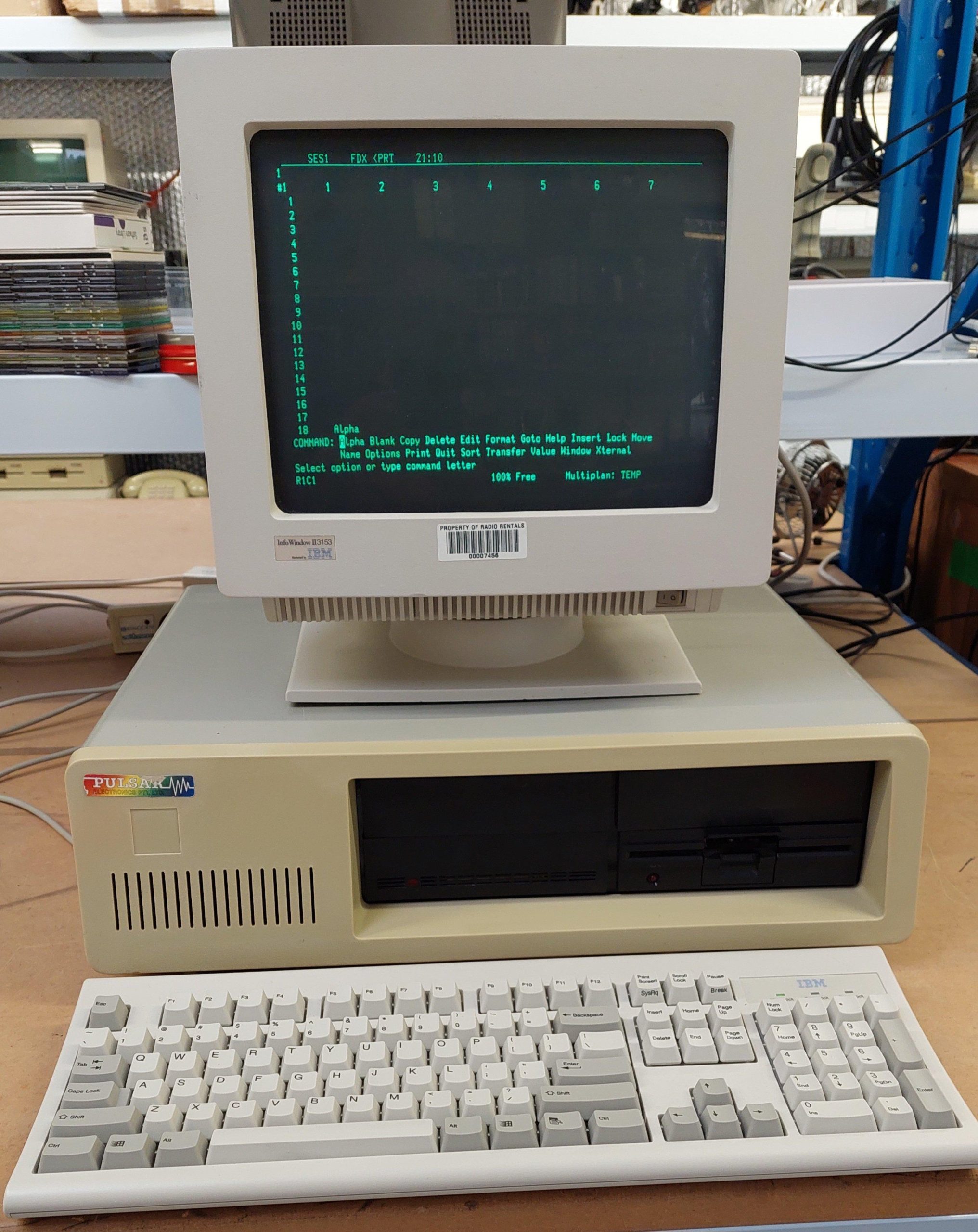
Inside the IBM PC style enclosure are 5 little big boards – one of which acts as a master to control drives and printers. The monitor is an IBM terminal, which is much younger than the computer.
The other four little big boards support 4 users via serial terminals. Each of these is connected back to the master via a serial line. These cards all run TurboDOS. Each provides 64kB of memory for running CP/M programs.
The master provides access to a floppy disk drive and a SCSI hard disk – emulated with a SCSI2SD.
I connected it up to a serial terminal, but I couldn’t get anything out of any external serial port. The hard disk did not spin, so it may be a lost cause.
I had no boot disks for the floppy disk, although i thought it may be possible to create some from the 8″ disk collection. Many of the disks were related to Pulsar – both CP/M and TurboDOS.
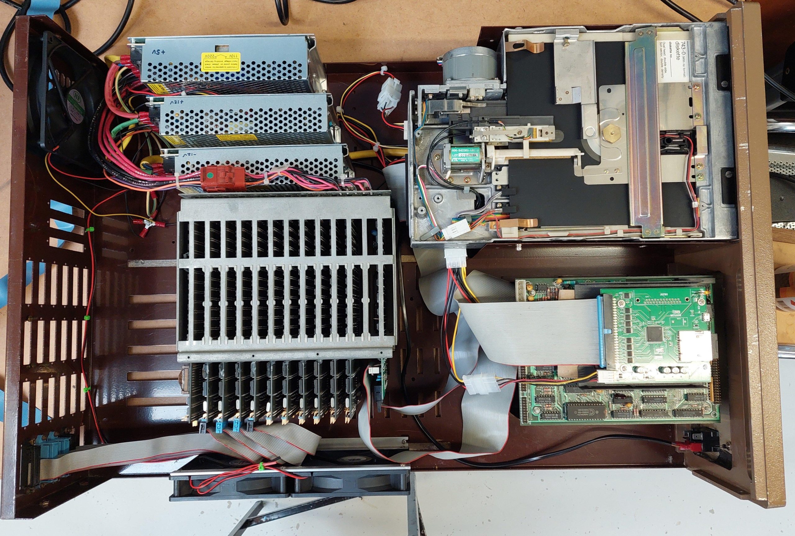
Working in the case was a little cumbersome, so I pulled the system right down to the boards:
It consists of:
1x Master LBB with STD and Floppy Drive Interfaces
4x Slave LBB (with a variety of options which are probably not used)
2x SASI/Dual Serial Boards
1x Mitsubishi M4854-342 High Density Floppy Disk Drive
1x NEC LR 56913Hard disk drive with Adaptec ACB-4000 SASI adapter
1x Sysquest removable disk drive with Adaptec ACB-4000 SCSI adapter (external to computer and mounted on its own baseplate)
Although the slaves live in the rack, they only use the bus for power. They communicate with the master via a serial line. Several tracks need to be cut to isolate the local slave bus. If the STD interface components are loaded, then even more need to be cut! There is also a further mod to serial port A for a remote reset and a serial interface clock. It’s all nifty but ugly at the same time.
There is a lot of variation amongst the slaves. Perhaps from card swaps over the years, or perhaps this machine was put together using whatever was in stock. Serial port connectors can be straight or right-angled, a bare header, or a shrouded header, sometimes with release levers. The right-angled headers used on Serial Port A (and the floppy disk interface on the master) have to be loaded 180 degrees from their correct orientation, resulting in pin 1 being incorrectly indicated on the connector. The notch is also in the wrong place!
One slave was fully loaded (STD interface and FDC), so i later swapped that board out for a minimal slave. There were a lot of track cuts to be re-instated before it could regain its full capability.
As mentioned, each of the slaves is connected via serial to the SASI/Serial cards. The master owns the bus and therefore the SASI/Serial cards.
There seems to be no reason why the slaves need to be in the unit – they could just as easily be located elsewhere, but there is not a lot to be gained as either way a serial connection is required.
The serial ports on the master were used for printers, although port A will become the master if a single user variant of TurboDOS is loaded.
I tested each of the boards with an MP7A Monitor ROM in a different chassis.
The master little big board does come up ok, so probably it was silent at switch on because that’s how the boot ROM rolls.
Two of the slaves were ok, but the other two were not working. One had a bad solder joint and the other had lost 12V connectivity because the track is very close to the board edge and was severed. The damage would have occurred when I levered the board out of the backplane (there was no other way).
I could not get the master to boot from the floppy disk, even after adjusting the phase-locked loop as per Pulsar instructions. I parked that board and used a spare, which did boot.
From there, the configuration tool was used to setup the slaves. There are a lot of questions asked about each slave. I took the easy options with automatic login of the privileged user.
The 7500 system uses a 5.25” drive rather than an 8″. As it turns out, the floppy disk drive in this unit, Mitsubishi 4854-342, is intended as an 8″ replacement – it even claims to be a 77 track drive although i suspect it’s good for 80.
The 50 pin host interface is connected to the 34 pin drive interface via a simple adapter. All up, this means that the 8” images can be written to HD 5.25” disks.
Looking at the simple 50/34 adapter board, I suspect that the drive has a couple of signals that may not be present on a 5.25” interface – Ready and 2Sides. I imagine that 2Sides is always asserted because there is no way for a 5.25″ drive to know if a disk is single sided. 8″ drives can.
The drive was cleaned and lubricated and tested ok with Imagedisk.
8” Pin
8” SIgnal
5.25” Pin
5.25” Adapter
Comments for Emulation with Gotek
2
TG43_L
Not used
4
6
8
10
2SIDES_L
2
REDWC_L
Not driven by controller or gotek. Pull down
12
14
SIDESEL
32
SIDESEL
16
18
HEADLOAD_L
4
Not Used
20
INDEX_L
8
INDEX_L
22
READY_L
34
DISKCHG_L
24
26
DS0
10
DS0
28
DS1
12
DS1
30
DS2
14
DS2
32
DS3
6
DS3
34
DIRC_L
18
DIRC_L
36
STEP_L
20
STEP_L
38
WDATA_L
22
WDATA_L
40
WGATE_L
24
WGATE_L
42
TRACK0_L
26
TRACK0_L
44
WRTPRT_L
28
WRTPRT_L
46
RDATA_L
30
RDATA_L
48
50
16
MOTORON
I wrote an HD floppy disk from 8″ disk image 8_257_02 (Pulsar Turbo V1.3 Master Configuration Sys 14 Config V24 Single User) using greaseweazle.
Pulsar was an Australian computing company located in Melbourne, Victoria. They made STD cards and computings systems based on the STD bus and often using TurboDOS.
TurboDOS is a multiuser/multiprocessor operating system that can execute CP/M programs.
Eight Z80 processors and two 80186 processors share an 8″ floppy drive and a SASI/SCSI hard disk, supporting 9 concurrent users. Each Z80 user gets their own 64k in which to run CP/M-80 programs, while the lucky 186 user scores 256kB in which to run CP/M-86 programs.
The master board, a 80186 board, loads the operating system from disk and, once it is up, it transfers the operating system to each of the slave cards.
All the rack-mounted cards are bona fide eighties cards. The rack and the 8″ drive are also of the time. The re-construction is new. I was able to find only very scant details of the Pulsar 9000, but i did have a complete set of cards and some software handbooks. It looked like a project!
I refer to this system as a Pulsar 9000, but is actually really a loose interpretation of what a Pulsar 9000 might have been. It arrived as a collection of STD boards made by Pulsar, some STD subracks, some Pulsar enclosures, some TurboDOS manuals, some 8” floppy disks, and a few notes, brochures, price lists etc.
The work on the Pulsar 7500 helped to give some insights into how TurboDOS is used on a multiprocessor system, but this is a step-up in complexity and with less documentation. In particular, the specifics of how to install TurboDOS were missing.
The 7500 used Little Big Boards and SASI/Serial cards, and it arrived as a system. There was manual that confirmed the arrangement and how to boot it.
The cards had no labelling that indicated what they were, but matching the components with some brochures and price lists helped to identify them.
Amongst the cards were:
2x STD-6016 80186 CPU Cards – one with 256kB and the other with 1MB
10x STD-6080 Z80B CPU Cards
2x STD-6216 SASI Floppy RTC
The CPU cards were sold as masters or slaves. The type of card was probably just an EPROM change or jumper setting.
The STD-6080 cards are more powerful than the Little Big Boards in the Pulsar 7000. They have better inter-processor comms, including a network interface and through-the-backplane connectivity. They have no floppy disk interface.
Some of STD-6080 cards do not have the network interface installed.
The DIP switches possibly set the address of the card on the STD bus. Switch 7 appears to be the LSB. There are 6 cards that seem to follow a sequence of 0 to 5. There are another 4 cards that follow a sequence of 0 to 3. Perhaps two separate systems originally.
There is very little information available for these cards. There are some brochures but no manuals or schematics.
STD-6080 6MHz Z80B
The STD-6080 cards are more powerful than the Little Big Boards in the Pulsar 7000. They have better inter-processor comms, including a network interface and through-the-backplane connectivity. They have no floppy disk interface.
Some of STD-6080 cards do not have the network interface installed.
The DIP switches possibly set the address of the card on the STD bus. Switch 7 appears to be the LSB. There are 6 cards that seem to follow a sequence of 0 to 5. There are another 4 cards that follow a sequence of 0 to 3. Perhaps two separate systems originally.
There is very little information available for these cards. There are some brochures but no manuals or schematics. Some of the boards have the serial network driver – others don’t. I don’t intend to set up a serial network at present so it doesn’t matter much.
Based on the settings of the cards, the DIP switches operate as follows:
Switch
Function
Setting
8
Master/Slave
Set to On
7-3
Slave ID
On=0, Sw7 is the LSB. 0000 is slave number 1.
2
May be a part of slave ID. Not sure!
1
Don’t know. Maybe determines the network interface?
Set to On
These seem to be similar for the 80186 boards as well.
There is a 256k board and a 1MB board. The 256k board is labelled “master only”. I tried it as a slave, and although the boot sequence seemed to complete ok, there was no output from the serial port.
Before launching into a full build i decided to spend some time testing stuff out. Did the critical cards work? Did i have all the required disk images? What combinations work? Could i use a SCSI drive emulator with the SASI card?
I set up a small STD card cage with a power supply and used a 5.25” HD density 8” substitute drive for checking out the disk images. Disks were written with greaseweazle.
All the files, including the TurboDOS 1.4 Manuals and the Pulsar disk images, are available at the Microbee Technology Repository
Both STD-6016 80186 boards will boot from disk 8_287_01 using a STD-6216 SASI card.
The configuration utility on the boot disk allows setup of STD-6016 (80186) and STD-6080 (Z80B) slaves.
Adding a second 6016 board with the same configuration does not boot. Changing the DIP switches 8 on the second board allows the master to boot.
None of the STD-6080 boards will boot from their native disk, 8_288_01. They all boot as slaves to a 6016. There may not have been a master configuration boot ROM, or the configuration may be via a dip switch. This disk may not have boot tracks.
Once the system is configured to use a slave, the master is no longer available as a console.
The STD-6216 works with SCSI2SD, but I have not been able to boot from the SCSI2SD. BOOT looks like it can copy the boot tracks but no success. Perhaps some SCSI2SD tweaks might get it there.
The system won’t boot from floppy if the SCSI disk is on. It may be attempting to boot from the SCSI disk but failing in a big way. There is a SCSI2SD parameter to delay startup.
To configure the STD-6080 slave, the CONFIG program needs to be able to access the distribution files for the STD-6080 – particularly PROSLV8.SYS. I did this in a single user configuration by setting up the hard disk first and then copying over the STD-6080 files.
The STD-6080 slave cannot run the STD-6216 executables, so on startup it has to have access to its own files. It’s possible to switch to the master using MASTER, but there seem to be some limitations, eg the config program seems to gag. It’s fine with the 1MB card so perhaps less limitation with that card.
The distribution disk does appear to have a master system for the STD-6080, but I don’t seem to have ROMs to load it – unless it’s by configuration link.
A gotek is a more convenient and reliable option for loading programs from disk images than actual disks. I just load the HFE files onto a USB stick for the gotek and then use with a 50 pin to 34 pin adapter to connect.
A gotek will never match an 8″ drive for beauty!
Where required and possible, the terminal option has been configured for Televideo 925.
There are two hard disks that came with the rest of the items. One was in the drive rack and the other was stored separately. The latter was clearly marked as being TurboDOS for the 80186.
Drive
Label
Capacity
Configuration
Speed
Status
Miniscribe 8425?
TurboDOS 80186
21MB
4 Heads 615 Cylinders 17 Sectors/Track
68ms
Boots 7 bad sectors marked
CMS Enhancements (Kalok) KL 320 Octagon
21MB
4 Heads 615 Cylinders 17 Sectors/Track
48ms
Untested
At least superficially, these drives appear compatible. Neither are listed in the TurboDOS 1.4 configuration options, but there is an option for a Miniscribe with similar parameters.
Both of the disks have MFM/ST-506 interfaces. The Pulsar 6216 has a SASI/SCSI interface. An Adaptec 4000 adapter board converts the drives to SCSI. The configuration program is aware of the adapter.
It was a bit of a surprise to see the machine boot from the miniscribe hard drive, as it probably hasn’t been powered for about 35 years.
It booted up to a user prompt. I was able to guess a user (accounts). It had no password, but was not privileged. It threw a few bad sector errors.
I found a post that said that TurboDOS stores its user ids and passwords in userid.sys on user 31. Unfortunately, 31 cannot be accessed without being a privileged user. Fortunately, there were some backups on floppy disk.
I booted up with floppy disk and then changed hard disks and copied the userid.sys file to my solid state drive. I could then have a peek:
Then I changed back to the old hard drive and was able to login as system.
Once there, Verify was used to check for and mark bad sectors:
Stat returned:
This system has disabled all floppy disk drives except A. There are two partitions on the hard disk B: and C:.
The baud rates are set to 19200 with 7,1,E.
There are 4 Z80 slaves.
There’s a fair chance that the hard disk will die. Often they power up ok to fail in the next month or so.
I tried copying the boot tracks using Boot, but the SCSI2SD drive will still not boot. There must be a trick.