Inspection of the first chassis showed no obvious issues so i removed all the cards, disconnected the drives, and bravely powered up it up. The voltages looked sensible. There was no smoke.
I then put the cards back in and fired it up. Surprisingly, it came up ready for a boot disk. I tried my disks for the VT1303. Curiously the VT1303 word processor boot disk was labelled as also being for the RDS 201/202 and sure enough it worked.
The CP/M disk did not work. It booted but then reported that it was not for this system and then halted.
I found another image “Lexitron Raytheon VT Series CPM-85 Disks 1 & 2” Disk 2 that sometimes worked (I thought there were drive issues) and then I found CP-M 2.20D worked better.
The cataract issues were remediated in much the same way as the VT 1303.
I then started trying the cards from the second machine in the first. The processor cards appear identical, but CPM again reported that the system was incorrect.
RAM Card is good
Printer card is good
The first FDD is good
The second FDD does not read disks properly
After testing the disk cards, I had some problems getting the machine to start. This seems to have been the keyboard connectors. I gave them a clean (at both ends of the cable) and they came good. Symptoms included a continual beep or incorrect characters typed after boot, or random rubbish on the screen.
The system will give a start chirp if the printer card is missing, but will not start the boot process. The same if the second floppy disk controller is missing.
I repeated the exercise on the second chassis. The 5V line was 5.75V. It’s a switching supply. I found the voltage could be adjusted at the pot next to R75 – top right. Fully loaded it drops about 0.25V so I tweaked it up a little.
After cleaning a lot of edge connectors, this system also came up. Remarkable really. As noted earlier, the processor card does not work with the same version of CP/M as the other machine. I swapped the ROMs and it came good.
These are 2708 ROMs which are a problem for me. I don’t have a programmer that can read or write them (it on the “to be acquired” list). I adapted my EPROM programmer. I can now read 2708s through an adapter. I used a 2716 in the processor card with a hand made adapter.
The bottom line is that the two sets of cards are good except for one floppy disk controller.
This is a long technical post. There’s probably only one reason to read it: you have a Lexitron with a broken keyboard. I’m not going to polish it much, but I leave it here just for you!
I spent a lot of time creating a teensy replacement for the microcontroller in the keyboard. One of the great challenges was to work out the key codes sent from the keyboard to the 8085. This was very time-consuming and there were some that I never really cracked.
With the arrival of working keyboards, I could just swap out the original for one of the working units. Buuut the teensy solution actually provides a mechanism to move data from a modern PC to the Lexitron and that’s handy. Also, I guess I’d like to just close the loop!
I can now sniff the communication between the 8085 and the keyboard microcontroller. Because the keyboard appears to be just another device on the 8085 bus the data is transmitted as a parallel byte. This would be easy to sniff with a logic analyser, but not so easy with an oscilloscope. I thought my Analogue Discovery 2 might be sufficient for this task.
Two Different Keyboard Types
One of the VT202 units uses the same Cortron Keyboard as the VT1303. The other uses a Digitran keyboard which looks quite different but seems to be entirely compatible with the Cortron. The Digitran sound is not as loud.
Revisit Operation
Keyboard Pinout
Pin
Name
Function
1
+5V
2
+5V
3
GND
4
GND
5
NC
6
GND
7
Strobe_L
This line indicates activity on the keyboard. It is asserted for 5us when a key is pressed and for 10us when a key is released. The strobe is not asserted when a front panel switch is changed. It is not asserted when the shift key is pressed. It is asserted for spec shift.
8
D5
9
D6
10
GND
11
D7
12
D4
13
Kbd_Read_L
This line causes the keyboard to put data on to the 8085 bus. The read occurs about 100us after the strobe is asserted. A0 is low. Scan code? A second read occurs about 8us after the first. A0 is high. Switch state? This strobe is asserted a couple of times every 10ms (approx.)
14
Screen On
This also appears in the status register.
15
A0
This selects the data that is read by the 8085 – either the keycode or the status of the front panel switches.
16
Kbd_Write_L
This strobe is asserted about 5us after Read is asserted in response to the Strobe. This strobe is asserted every 10ms (approx.)
17
Reset?
18
GND
19
D3
20
D2
21
D1
22
D0
23
-15V
24
-15V
25
+15V
26
+15V
Character Register
Bits 6:0 = Character number

Bit 7 = Shift
Status Register:
Bits 1:0 = Print Spacing

Bit 2 = Pitch

Bit 3 = Screen Spacing

Bit 4 = Not used (input pulled up)

Bit 5 = Key pressed

Bit 6 = Screen On/Off

Bit 7 = Autorepeat (although it doesn’t seem to be used)
Command Register:
Bit 0 = Key click

Bit 1 = Type Through LED

Bit 2 = Select LED

Bit 3 = Continuous Typing LED

Bit 4 = Write LED state (Bits 1, 2 & 3)

Bit 5 = Acknowledge

Bit 6 = Bell (Not supressed by volume control)? Under CP/M this is sent when Select is pressed.  Select causes an alarm chime (not volume controlled).

Bit 7 = Unknown
Adjustable volume applies to key strokes. Alarms have a fixed volume.
Word Processing Program Behaviour
Periodic
Once every 10ms or so the program reads the status register and writes the Command Register.
Keystroke
When a key is hit the keyboard alerts the uP by asserting Strobe_L for 5us. The program responds by reading the character, reading the status register, and then writing 32 to the Command Register. This seems to be an acknowledgement. If there is a LED change or sound then that will be sent a few milliseconds later.
The key release is also acknowledged with a command write which can update the LED state and sound a bell but I think does neither.
The unit only autorepeats on space, backspace, dash, underline, and full stop. This auto repeat is convoluted. It involves resending a specific character after the wait time has elapsed. This triggers the software to autorepeat. It looks like the bit 6 of the status word is set at the same time. This is set by an output from the microcontroller (Pin 29). Although the original keyboard does this it does no appear necessary.
Character
Original Output
Autorepeat Output
Space
80
112
Dash
103
119
Underline
231
247
Full stop
26
122
Backspace
110
126
I can’t see any obvious pattern in these numbers. They just are.
CP/M Behaviour
Periodic
Once every 10ms or so the program reads the status register.
Keystroke
When a key is hit the keyboard alerts the uP by asserting Strobe_L for 5us. The program responds by reading the status register, reading the character, and then writing the Command Register – it can acknowledge, set LEDs, or make a sound.
The key release is also acknowledged but the LED data is not repeated. There is no periodic write The key release is also acknowledged with a command write which can update the LED state and sound a bell but I think does neither.
CP/M autorepeats on most keys but not Spec Shift or Sel. It initiates a beep on each auto repeated character.
CP/M politely ignores the autorepeat shenanigans that the keyboard does for the word processing program.
In CP/M lots of keys are defined as function keys that can be changed using the config program. The config can also control auto repeat and key click.
Select is a caps lock key.
My Current Keyboard Code
The current routine that I have for sending a character to the 8085 sets up the character and then takes then asserts the strobe (indirectly) for 1ms. It then sets up another character (usually zero).
The real thing asserts the strobe for 5 or 10us. Both the key register and the status register are read within about 100us of the strobe. The Command Register is then written. This may be the trigger to clear the key but maybe not. I previously concluded that the key needed to be nulled but I’m not sure why it does.
My implementation autorepeats on all keys except “mode” keys like Spec Shift and Margin Set. The actual unit does not autorepeat, although the software does under some circumstances.
I’ve treated Spec Shift and Margin Set as special cases because they are used in combination with other keys. Certainly, autorepeat doesn’t apply. CP/M treats Margin Set as a normal function key.
This means that the effect of these keys is application specific. Eg in CP/M the Spec Shift key is used to create control keys eg Ctrl-C to do a soft boot. In the word processing program it has no effect on the letter c. Spec Shift does not beep.
Shift really is different. No key code is sent with just the shift key, and the character that is sent is modified if a shift key is pressed. When shift is pressed the most significant bit is set. This applies to all keys including Spec Shift and Margin Set.
The various reads and writes change a little with CP/M. CP/M still reads the front panel switches but I have no idea what it does with the state. Similarly, the LEDs have no apparent function.
Under CP/M Select behaves like a caps lock. The shift is done in software.
Observations
Key hit
Close up of subsequent reads and write.
With the autorepeat:
The regular status read (word processor software):
Revised Keyboard Code
The keyboard code has been substantially reworked based on the observations that were possible using the logic analyser function of the Analogue Discovery 2.
Autorepeat has been removed except to the extent required by the word processing program.
Each key press and release is transferred to the 8085.
The timings have been changed to better match the real keyboard.
Only one key is checked and processed on each pass of the main loop so that commands are less likely to be missed.
All sounds are generated only at the request of the 8085. There are no automatically generated sounds.
An additional signal was discovered that is set when a command is written and is cleared when the command has been read.
A few missing key codes were found.
Things like Spec Shift, Set Margin, and Select now work as advertised (as far as I can tell).
The code works on the VT1303 and the VT202. It works with the word processing programs and with both the VT1303 CP/M and the VT202 CP/M.
Mapping
The transmitted codes can be read straight off the data lines (see waveform pics above).
I have a couple of working Lexitron word processors that run the CP/M operating system. They use an unusual disk format for which i have no means of decoding or encoding. The only input that these machines have is the keyboard which is a somewhat tedious means of transferring programs and data. This has limited the applications that i have been able to transfer to these machines.
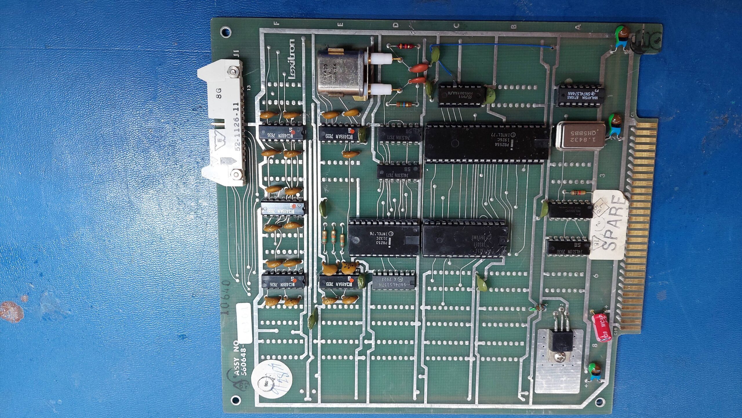
Documentation and the CP/M implementation both suggested that Lexitron produced a communications card that could do asynchronous serial communication but i had never seen one. Recently i did a search on ebay, and discovered a card that was likely to be the unicorn communication card so i snapped it up. It arrived from the UK within a couple of weeks.
It has a 8251 programmable communication interface (PCI), an 8253 programmable interval timer (PIT), a 8255A programmable peripheral interface (PPI), and an MM5307 baud rate generator (BRG). It has a lot of RS232 drivers/receivers so i suspect that a bunch of parallel port lines use them.
I couldn’t be sure that this was the right card for either the VT1303 or the VT202 but i crossed my fingers and took the lid off the VT202.
Looking at the relationship between the PCI and the drivers/receivers, the pinout on the DIP connector was consistent with the usual RS232 pinout. The connector allows for external transmit and receive clocks, but there is some logic which allows the PCI to also use the clock from the onboard baud rate generator.
The card seemed to be in good condition. I checked for shorts on the power rails but found none. The spare slots in the card frame a little different to the slots that are home to the other cards, but the affected pins were not in use by the communications card.
Unfortunately the card developed a short on power up, resulting in the -15V fuse blowing. After replacing the offending tantalum capacitor and the fuse, the system started up ok with the board present.
I ran the configuration program on the CP/M disk to set port to 9600, no parity, one stop bit, 8 data bits. I also set up pun: and rdr: to use the serial port. I tried to get it to transmit data using:
pip pun:=rdr:
Alas, there was nothing so i started checking things out – which is a little laborious without an extender or a schematic. I did confirm that the card accessed both the PCI and the PPI, which i took as a sign that it was the correct card.
The PCI transmit/receive clock was missing and this was because the BRG was not oscillating. Everything around it looks ok:
Power lines
Crystal connected
Parallel control inputs from PPI changing as they should
Capacitors values are plausible
Currently, i’m concluding that the IC is dead which is a shame because it’s not easy to get.
In the interests of progress i pulled the IC and provided my own clock from a lab waveform generator. Frequency= 9600 x16 = 153.6kHz.
Lo and behold, there was communication:
Although the BRG is disappointing the overall result is very good. I can either knock together an emulator or try to source a replacement.
Before charging in, i decided to see if it was just the oscillator that was at fault. It would make life easier if the divider was still a going concern. I configured it for an external oscillator – again provided by a waveform generator. This seemed to work ok. It is possible that the oscillator fault is due to the crystal and the IC is actually fine.
Given some uncertainty about the crystal characteristics, testing that hypothesis seemed more trouble than putting together a replacement oscillator. There are plenty of spare footprints on the board.
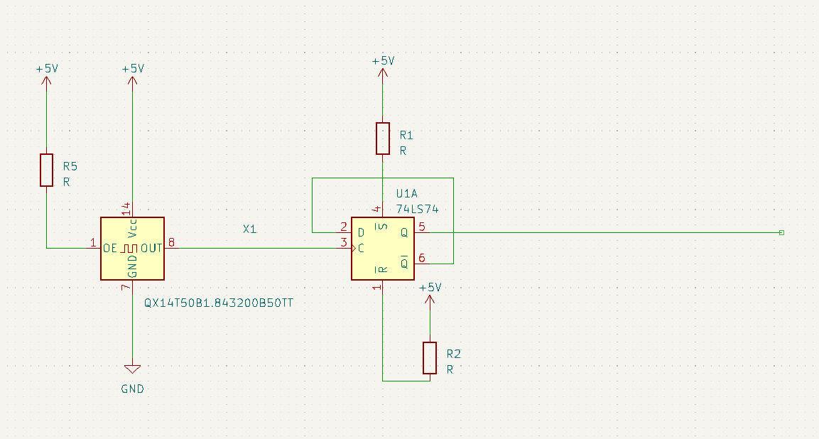
Oscillator modules at 2x 921.6kHz = 1.8432MHz so i settled on that frequency. A flip-flop will divide by 2.
I built up the mod above and reconfigured the baud rate generator to use an external oscillator. It worked fine. The oscillator and divider are in the bottom left hand corner.
Unfortunately, i have found that the xon/xoff does not seem to work with data being sent to the lexitron. The configuration program does call the setting “output flow control” so i guess i should have been forewarned!
This means that i will either need to write a transfer program or adapt kermit to this machine – or i suppose i could attempt to write my own driver. I think the best course of action is to adapt kermit. I’ve never done that before and if i learn i might be able to make a version for the Osborne Executive as well.
The operating system seems capable of setting up the communication parameters so i would just need to correctly set the address of UART on an 8251 version of kermit.
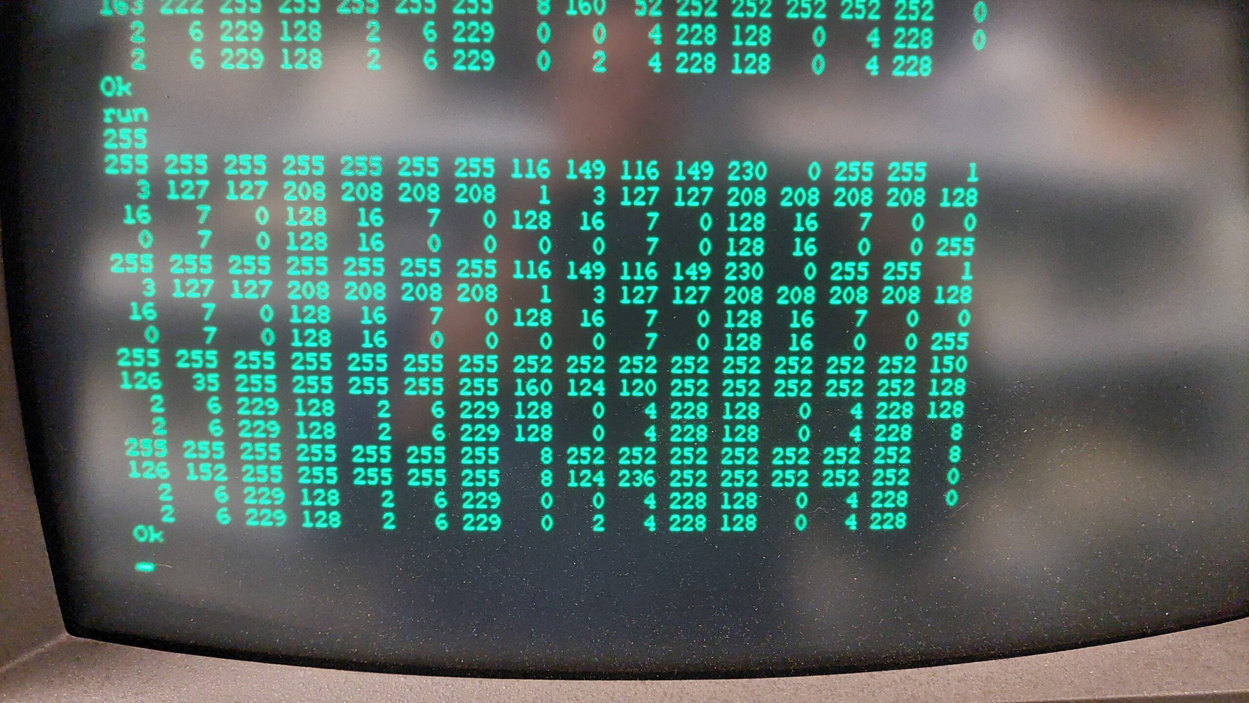
The first thing i need is the base address of the UART. I wrote a little basic program to read all the I/O locations and sent a character to the UART from a PC with the hope that it would appear in the data register of the UART. Sure enough it did “t”=116. It is at 48H and again at 4AH.
Actually, i may be able to use the generic version of kermit. In doing a bit more reading i see that there is a generic version that uses operating system calls. This version relies on the the CP/M IOBYTE being used by the Lexitron OS version. There is a speed penalty from using the generic version but i could live with that for now.
Kermit80 is distributed as a common part (CPSKER.HEX) and a customised part. The generic part for CP/M 2.2 is CPVGEN.HEX.
The initial transfers to the target machine are a little tricky because i needed to rely on the tools that were already present on the machine. In this case i have a serial port that can be accessed with PIP.
In principle, it should be possible to transfer hex files fairly safely using PIP as long as the OS supports XON/XOFF flow control. I’ve already discovered that this support is limited. That means that there is a risk that the computer will not keep up with the data. I experimented and found that it was quite reliable at 2400 baud unless the machine got distracted by some other I/O eg a disk write.
I had previously found that PIP has quite a good buffer and that 4k of data translated to hex (ie about 12k of text) does not trigger a disk write during the transfer.
CPSKER.HEX weighs in at about 70kB. I divided it up into 6 files and transmitted each one using kermit on a PC and PIP on the Lexitron.
Because the disks don’t hold a lot of data and the hex files are inefficient, there is some disk juggling to be done. I find it convenient to create working disks with a boot track and PIP, STAT, and LOAD. Two of these gives sufficient working space.
At the Lexitron i configured the serial card to use 8 bits, no parity, and 2400 baud and received with PIP via the RDR: device:
B> a:pip kerm0.hex=rdr:
At the PC:
Kermit> set port com4
Kermit> set baud 2400
Kermit> transmit cpsker.hex
Once the transfer is complete it is necessary to connect to the Lexitron as a terminal and send an end of file character, Ctrl-z.
I repeated this for kerm[1..5] and also for the custom file CPVGEN.HEX.
Then the files can be concatenated locally with PIP:
At this point the files are ready to be converted to an executable. The standard LOAD program can only do one file at a time. The kermit411 distribution includes a more advanced load, MLOAD, as a small hex file. I transferred it in the same way as above and then converted it to an executable:
B> load mload
And then created the kermit executable:
B:> mload kerm411,cpsker
B:> kerm411
Kermit on the Lexitron requires some setup:
Kermit> set port tty
Kermit> set file binary
Note that the baud rate is already set by the OS config program.
Then any file can be transferred using send and receive. I sent pacman95.com as a test. The terminal characteristics aren’t quite right, but it got there.
It does not sound like much, but this is a very important step forward for the Lexitron ecosystem. I should now be able to transfer a bunch of generic CP/M programs and data.
Using the terminal mode in kermit on the Lexitron is a little complicated by the unusual keyboard. I could connect using “connect” but i could not find the exit key. Shift-Menu does provide a menu though, and this does have a command to exit. More experimenting required.
At the PC end, timeouts occur during disk writes. The length can be increased to, say 10s, at the PC end with:
Kermit> set transmit timeout 10
The error limit can also be increased at the PC end:
Having got Kermit running on the Lexitron CP/M my attention could turn to adding some more applications. The Lexitron does have the limitation that it uses an 8085 microprocessor and that rules out any apps that assume a Z80. This seems, for example, to include Turbo Pascal. The Lexitron also uses 35 track single sided drives; the space available is only 140kB which is tight.
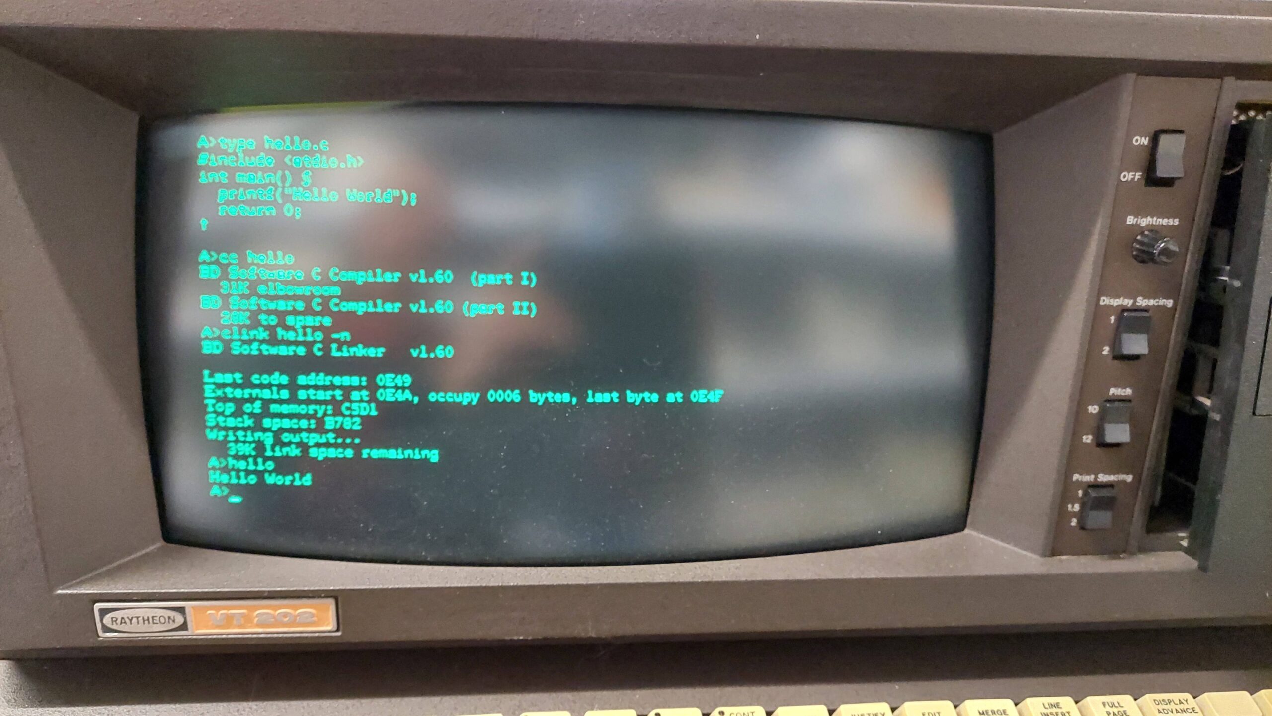
BDS-C was written for the 8080 and doesn’t require a lot of disk space. The author’s website provides the software, sources, and various other files for the last version, 1.6. It also has a video where he talks about the history of the compiler and more:
i was able to transfer the files to Lexitron floppy disks by means of kermit. Once i had set up a disk with just the essential items it was good to go.
I started to punch in hello world and then realised that there were no braces {} on the keyboard. I eventually worked out that the ascii codes correspond to some unusual characters that the Lexitron uses so i just used them in place of the braces.
I set the monitor aside as a separate project. It had very crude and broken mod that held a sheet of coloured perspex over the screen. I will eventually add that back.
The main unit was in good shape. I just reseated the main RAM.
To judge from the date codes, it was made in 1981 when I was still at high school.
This machine uses an old school linear supply. I inspected it and reformed the power supply capacitors by bring up the supply voltage slowly with a variac.
Two new keys where the second shift key was. The sideways A is the tab key.
Switch added at the top of the pic. Shift changed to backspace. Backspace to clear.
With power (and a kludge for the video cable) it came to life.
The plastic had melted against the soft plastic dust cover. It looked pretty awful.
I had to make some compromises. I used a combination of acetone and wet & dry paper to get it back to an acceptable finish. It may be possible to do better.
I crafted, and then glued on, a replacement door latch. It failed, so i had a second go and that is still holding several years later. To be fair, i don’t use the cassette deck very much.
The tape unit itself was gummed up, but after a clean and lube, it seemed like it might work.
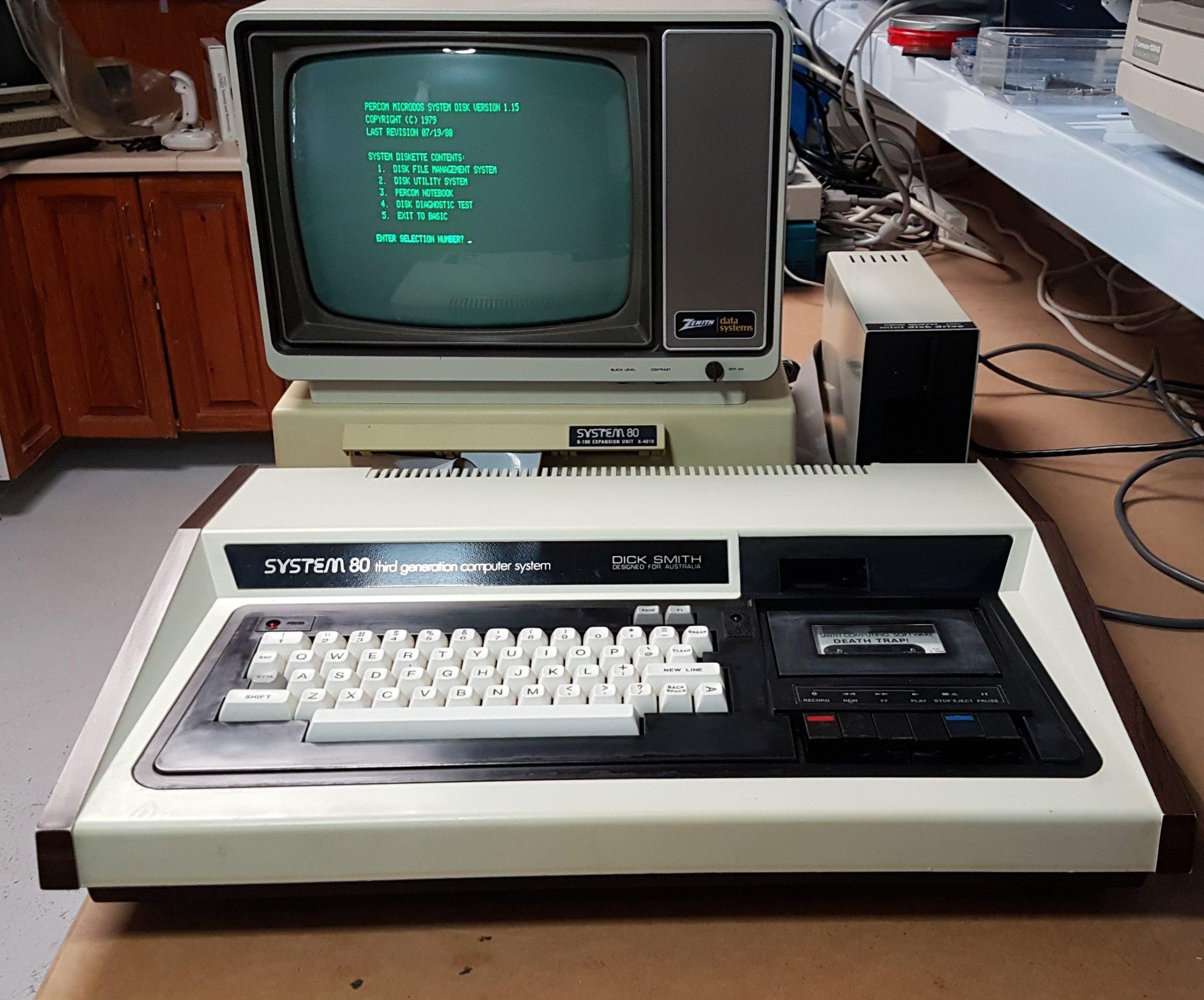
The System 80 is an attempt, largely successful, to create a machine compatible with the TRS-80 Model I.
Terry Stewart has done a wonderful job of documenting the System 80. Everything that you could ever want to know about it is there. I’ll just focus on my own experience.
I bought this machine from a colleague, Scott, at the Adelaide Retro Computing Group back in 2020. My recollection is that he had collected a number of computers from a seller. This one was outside his interests, so he offered it for sale. I was happy to take it; i never expected to have such an opportunity.
The machine came with an expansion unit and a floppy disk drive. The expansion unit, X4010, has a three slot S-100 backplane. It provides 32k of memory, a disk controller, RS232 port and printer port.
The machine can run any of the myriad of operating systems that were created for the TRS-80 Model 1. Similarly, it can load programs from cassette, just as the TRS-80 Model I can.
This particular machine is an early version with no tape level meter. It has a keyboard modification that replaces one of the shift keys with backspace and tab keys.
It came with a soft plastic dust cover. Instead of protecting the unit, it caused a lot of unsightly “melts” in the plastic. There were also several other issues to work through.
The computer is badged as a “third generation computer” but, as far as i can work out, it would normally be considered a fourth generation computer. Perhaps the usage of the term changed. Or perhaps it is the only example of “underselling” in the computer industry.
There were two different types of expansion units for the System 80. This is the early one with the S-100 bus.
The first card connects to the System 80 via a 50 pin interface. It also provides the floppy, parallel and RS232 ports. I particularly like the termination networks that have been added to several of the ICs.
The second card provides 32k of RAM. There was one faulty RAM chip.
The power supply unit is the same as the computer. I reformed the caps with a variac.
There is one spare slot for an additional card but the case is not great for adding additional I/O and there’s no obvious mechanism for adding more memory beyond the current RAM/ROM.
The system came with a matching Floppy Drive Unit that connects to the expansion unit. It uses an MPI B51 40 track single sided drive.
I gave it the routine clean and lube, but it would not read disks. Drive speed was good.
Configuration was preset:
I located a service manual on the net and that was very helpful for fault-finding.
I convinced myself that the differential amplifier (CA3054) in the read circuit was cactus and replaced it. With this, the system booted. Alas, it wouldn’t format disks.
Breaking out the CRO and checking the signals on the drive interface showed there were no index pulses. In an unexpected twist, it turned out that the disks i was using were not sufficiently opaque. Is that even possible?
It appears so from the traces; the voltage in the top picture never gets high enough to flip the comparator, whereas in the second picture, with a different disk, it does.
I checked over and over. It’s fine with five other brands, so I’ll call it good enough.
It lasted about a week before it stopped reading from disks. Perhaps it had an intermittent problem and the original differential amp didn’t fix it.
With the scope, I was able to see differential signals going into the LM311 comparator, but nothing coming out. I replaced the comparator and i was back in business.
I made up a few disks and had a play!
I also had no trouble setting up a gotek as a drive. I just powered it off the real drive and connected with a custom cable. It has to be set to drive 1.
A couple of my colleagues, Mike and Craig, and i represented the Adelaide Retro Computing Group at the BSides event in May 2025.
They gave us half of a very large room at the Adelaide Hilton. Between us, we had about 15 retro/vintage machines for the cybersecurity community to experience.
The scene below is how things looked just prior to the start of the second day.