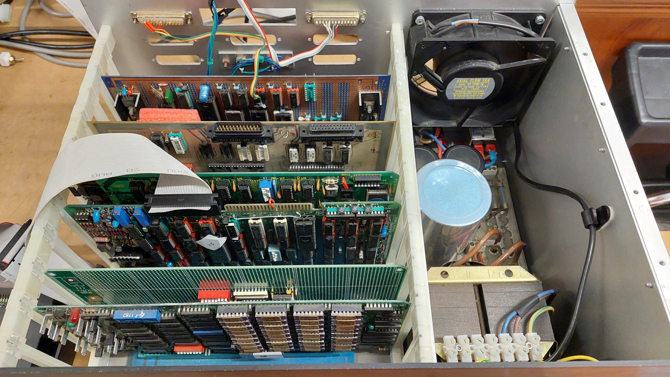
Wishing to be able to run the disk checks properly to be able to run lots of processes, and haunted by the thought that more memory failures can be expected on the 512MSU, i again turned to a modern solution.
This time it was a static memory board designed by John Monahan:
I could have gone for the full 16MB and filled the address space but i wanted to keep the 512MSU so i built an 8MB version. The existing memory could be moved just by changing some DIP switches on the MCU.
This project would probably still be pending but for a bare board being up for sale in South Australia.
If a generic memory board is used instead of the MCU/512MSU then:
It must support a Phantom signal
The 16FDC needs to be modified to provide a Phantom signal
The Phantom signal needs to either be on a different pin from the normal 67 or the DPU needs to be modified to not use pin 67 eg by cutting pin 6 of IC 41. It’s probably better to modify the new board to use pin 69 and be consistent with other group members.
I think it may still be possible to use the DPU as well if the memory card is 4MB or 8MB. It just needs to be located after the new board. It can’t go before because the board boundaries are not fine enough.
The SRAM is expensive at over $10 per MB. In the end it was easier to get the 4MB parts and two are required so I built an 8MB variant.
This card will be located at 0000H-7FFFFH. The 512MSU will be at 8000H-87FFH and the DIP switch will need to 01000.
The biggest challenge with building the board is mounting the TSSOP packages. I used paste and hot air and cleaned up the excess with solder wick. There were some troublesome bridges one of which only cleared after reflowing with hot air.
I had a look at the PAL equations just to make sure they would work with 8MB.
/S100_8_RD_OE@      =      /RD8@  * bA0   * BOARD_SEL * /pSYNC                  ;U19, 8 Bits to CPU, odd/high address
                         + /RD16@         * BOARD_SEL * /pSYNC                  ;Any 16 bit data Read
                         + /WR16@         * BOARD_SEL * /pSYNC                  ;Any 16 bit data Write

/S100_8X_RD_OE@      =     /RD8@  * /bA0  * BOARD_SEL * /pSYNC                  ;U31, 8 Bits to CPU even/low address
There seemed to be no interest in the address lines ie this board is selected regardless of the address (except for the phantom). For a 16MB card that would be correct. And it doesn’t matter for writes as long as all of the address lines are in use at P101 – this should just cause a write to RAM that isn’t loaded. But it would cause a read contention with a board in the top 8MB eg where I want the old 512kB to be.
I think that for my situation GAL5 so that /BOARD_SELECT is asserted only when the for the first 8MB.
It took hours to run the 68k RAM test in CDOS, but it was successful. 8.5MB of RAM was good to go.
cromix.sys had to be regenerated with an updated sysdef. After this there was abundant memory! There are a bunch of tweaks that i could do to take further advantage of the memory and i think a RAM disk could also be added.
An enthusiast build – and i couldn’t even be sure that it’s complete.
Andrew, a friend from the ARC Group, has supplied me with a lot of funky gear including a box of S-100 cards, a couple of chassis, several 8″ floppy disk drives, and about 500 8″ floppy disks.
One of the challenges is that the relationships between all this kit was not obvious. This one i was only able to sort out because i found the source for some boot ROMs on one of the floppy disks. Even now i’m not sure if i have the original RAM card but the one i’m using does just fine.
It uses the following cards:
Compupro 8085/88 CPU Card
Jade DD Floppy Disk Controller
A handcrafted wire-wrapped Serial & Parallel I/O and Speech Synthesiser card
A parallel card with real-time clock
Intersystems 256KDR
A recently constructed EPROM Card
I have not connected an 8″ drive to it as yet, but it boots JADE CP/M 2.2 from a gotek. The disk images are from the original floppy disks.
This machine is a reconstruction of a hobbyist built machine from the early eighties. It came to me in pieces in amongst a lot of other gear, so it wasn’t obvious to me that there was a complete computer there at all.
I had already rediscovered a Cromemco based computer which used half a dozen of the 29 S-100 cards that i’d received. I also had a rack, some 8″ drives, and a lot of 8″ disks which i had previously imaged.
Many of the disks were labelled as being Jade, and there was indeed a JADE DD Floppy Disk Controller amongst the cards. There were many more disks that used the JADE format.
There was also a Versafloppy II Floppy Disk Controller card, for which there were also a number of disks.
These were all CP/M disks so i was looking for a 8080, 8085 or Z80 processor board. The candidates were a Cromemco SBC which wasn’t a great fit with CP/M or a CompuPro 8085/88 CPU card which would work.
I also expected there to be some I/O and a card for a boot ROM. And RAM of course. There weren’t a lot of clues from the cards themselves.
Fortunately there was a disk labelled “Jade System BIOS Development which contained some assembler files for the CP/M bios and the boot ROM. At this point, i ruled the Versafloppy II out.
The boot ROM code had some comments identifying key components (8251, 8255 and 8253) on a W/W card. Once i found the card with that combination of components, i realised that W/W stood for wire-wrap. It was a hand-crafted board. It also has a speech synthesiser chip!
Looking at the chassis, i could see that the wires dangling from the back panel married up with empty sockets on the board.
A little while later i realised that there a couple more ports which may belong to this unidentified card:
It has a real-time clock on it.
I had several memory cards that could potentially be used, but given that the CPU card is capable of addressing more than 64k, i started with an Intersystems 256KDR.
This card is probably overkill, and i may swap it out in the future.
I do have an EPROM card, but it is made for 2708 EPROMs which i can’t program at present – i would need a new programmer.
Instead, i built a new card using a modern S-100 prototype card.
I needed an EPROM board to complete this computer and i could not see any easy way to obtain an eighties era card, so i had to knock one together myself.
I started with an S-100 Prototype board designed by John Monahan. This has all the buffers etc that end up on nearly every S-100 card, so a lot of the hard work is done.
John’s board designs are available for anyone to produce (as far as i can tell) and they are easy to get in the States. Not so easy in Australia, but on this occasion a batch turned up in Australia so a bought a few.
I had what i thought was the boot ROM code on an 8″ floppy disk. I’d previously extracted the files so i could have a good look.
The boot code indicated that the boot ROM would be located at F800 and occupy 2k. The Jade DD floppy disk controller uses a 1k window at F000. CP/M is set up for 60k, so there is also 1k free at F000. The boot allocates this to a Micropolis boot ROM similar to the one in the Sorcerer/Micropolis System.
I allowed for an 8kB EPROM (2764). J1-3 sets which address lines are used for decoding. To get just the top 2k, J1=J2.
Switch 1 sets the address of the ROM: in this case 00F800: 0000 0000 0000 1111 1000 0000 0000.
The highest address line decoded is A18, so the ROM will reappear at 04F800 but I don’t expect to ever have that much memory. That allows room for 256k of RAM.
My design worked immediately … no, of course it didn’t! I made several mistakes and i had trouble driving the phantom line (which disable RAM at the EPROM address). I eventually settled on the following:
I programmed an EPROM with the boot code that i found on the floppy disk.
There’s plenty of space left on the prototype card for some I/O if i ever run out of things to do.
The Jade Double D is notable for being an intelligent floppy disk controller. The onboard Western Digital FD1791 FDC chip is controlled by a Z80 processor. The CPU communicates with the DD through a 1kB window.
Although the card includes a processor and 2k of RAM it has no ROM. Instead, code must be injected by the CPU card. The code is embedded in the CPU boot ROM.
The boot code assumes that the window address must be set to F400. The jumpers were already correctly set.
This card supports 5.25″ drives on a 34 pin interface or 8″ drives on the 50 pin interface. Eventually i will use 8″ drives with this machine, but in the short term i just wanted to use a couple of goteks (with Flashfloppy).
The images that i wanted to use are from 8″ disks. These work fine in the gotek but because the gotek uses the 34 pin interface there were a couple of residual issues. There are a some signals expected by the boot ROM and the CP/M BIOS for the 8″ drives that are not on the 34 pin interface.
The first is the RDY signal which is supported by Flashfloppy on pin 34. This requires a link on the DD from pin 34 of the 34 pin interface to pin 22 of the 50 pin interface.
The second is that an 8″ drive can detect whether a disk is single or double-sided – the index hole is in a different location. For this, i added a switch to assert or negate the SIDES signal depending on which image i had loaded. I later copied all of the single sided disk images to double-sided disk images to make things a little simpler.
This card had a couple of hardware issues. The first was two shorted tantalums. The second was that, for whatever reason, two sockets had been butchered, and the chips soldered to the socket pins.
The cards were popped into the rack, including a partially tested EPROM card with a boot ROM programmed using a file from one of the 8″ floppy disks.
The source showed that on start-up the first serial port to receive a space character would become the console and offer to boot from the Jade DD.
The boot ROM source indicated a serial port speed of 9600. I used an IBM terminal setup accordingly.
I started with a CPU, EPROM, and I/O cards and proceeded to discover the various mistakes i had made with the EPROM card!
Once i could see that code was being read from the EPROM i added the RAM board and the Jade Double FDC. I could see data coming out of the UART, but it wasn’t making it to the terminal and that was because a shorted tantalum on the Jade board had blown the -12V fuse.
Once repaired, i got the boot screen.
I hooked up a couple of goteks and on the second image it booted.
I stumbled on a SMB PCB (V3) for sale on ebay. This PCB is for a modern design using many old ideas. It provides address and data bus displays, status LEDs, single stepper, breakpoints, and some other facilities and debug features. To be honest, i thought the blinken lights might add a little visible interest to the 8085/86 system!
The board was designed by S-100 legend John Monahan.
The frequency display seemed a bit unnecessary, so i skipped that part.
The S-100 bus is quite a loose/adaptable standard, and i’ve found that a card may work well in a particular context but not so well in another. I found this one neede some customisation for my set-up. I’m not super experienced with S-100 so my notes should be taken with a grain of salt and certainly not as a criticism of the original designer. Sometimes too, i am guilty of not RTFM!
I found the breakpoints were unreliable. I think this was due to the address bus not being stable when the address was captured (a decoded output driving a preset on a flip-flop). I modified it to use the pstab signal which seemed to settle it down.
When i came back to this a couple of months later, I found that at break the displayed address was always one more than I had requested. This led to quite an adventure in trying to understand how breakpoints work. I also noticed that it often broke at random addresses.
When I looked, I found that the breakpoint does not take into account whether the cycles are read or write, or if it was a data or instruction fetch or I/O cycle.
I further learnt that the displays are only accurate when reading. That’s because they are transparent when the pDBIN signal is asserted. If the card breaks on a memory write, then the display isn’t meaningful.
The address is latched locally using pSYNC AND pSTVAL. This seems to be an approach adopted for V3 of the board. Previously, the lines were just buffered. The earliest that these can be grabbed is when pSTVAL is asserted. As far as I can see, this makes it very hard to get a RDY signal asserted before the rising edge of PHI in state BS2, particularly given the standard says that pSTVAL may not be asserted until that clock edge. Fortunately, the CPU card asserts it much earlier (about 80ns) so there was hope. Unfortunately, the address registers are triggered when pSTVAL is negated which is too late to guarantee that the XRDY signal will be asserted in time to take effect on the current cycle. Consequently, it moves on to the next cycle and then stops. This explains the address being one too late.
I have made some changes to try to salvage some useful operation. The first was to use the leading edge of the pSTVAL pulse to trigger the address latches, so the address is available locally much sooner. Getting through the registers, comparators, gates, and flip-flop chews through a lot of the available time.
The V3 design uses PHI_L in place of pSTVAL (apparently this was not uncommon on older boards, but I’m not sure why it was done here). Given that RDY is negated by an asynchronous set, it is important that the Address comparison is stable before it is gated through to the flip flop. That’s difficult to organise because that logic is responding to the local address change initiated by pSTVAL being asserted. I think the only robust way to do this would be to accurately delay pSTVAL beyond the propagation time through the address comparison logic. Very ugly.
I tried this to some extent by inverting pSTVAL twice but this is not nearly long enough. Even with an RC network I found it was not perfect – particularly once I attempted to filter out writes using sMEMR. Spurious pulses were generated as the addresses settled. Using typicals for the comparator network, suggests a delay of at least 50ns is required, and this is hard given the two delay gates only give about 10-15ns and the pSTVAL pulse is less than 100ns. I did find the spurious pulse from the address detection could be suppressed with a 560pF capacitor. This resulted in predictable operation in my system.
When I added sMEMR I found that a spurious pulse was always generated on the cycle after the write cycle that matched the break address (attempting to suppress with capacitance does not help here). I have not resolved this, so I have removed the sMEMR signal.This means that breaks will be triggered by writes.
The V1 design, which had buffers for addresses rather than registers, would have been better for my system because the addresses would be available to the comparator logic 70ns earlier – plenty of time to be sorted before pSTVAL arrived and enough time to get XRDY negated (at least with my CPU board). The standard does not allow any time between pSTVAL being asserted and the critical STVAL edge in BS2, so that would have been really tough.
Looking at the timing diagram in the standard, it dawned on me that pSTVAL may be asserted twice by some cards. The timing diagram seems to make that a possibility, but not a guarantee. This would be consistent with a comment on the card site that says that early cards used the inverted PHI as the equivalent of STVAL. So, perhaps the V3 SMB card assumes that PSTVAL is asserted twice. The Compupro card does not do this.
With two pulses, there is an additional edge available to clock the address registers well in advance of the second mandatory pSTVAL pulse. I think this must be what the designer had in mind. The second PSTVAL pulse (or, as in the design, the matching PHI low) is identified by being in association with pSYNC. I attempted to substitute pSTVAL* with PHI* but I could not get the timing right.
I reverted to my original solution above (italics) which relies on a capacitor to suppress spurious outputs (very dodgy).
560pF capacitor at U22-12
U3-5 connected to U10-11
U10-11 pin bent out of socket
U10-11 socket pin connected to U10-13
So I think the upshot is that the card assumes a two pulse pSTVAL and the Compupro does not provide it. It’s possible that I have other cards that do – so I’ll need to bear that in mind if I use it with other processor cards.
Moving on … This board has a daughterboard, for the displays, LEDs, and control switches. In hindsight, I may have been able to mount it directly on the card, but I didn’t. Instead, I used ribbon cables. I made it a little harder by mounting the connecters iaw with the silkscreen, rather than putting them underneath.
The mechanical exercise of doing the front panel was quite time-consuming. I replaced the existing front panel with 3mm aluminium and 3mm clear perspex. That allows me to put card in between – a graphics design problem in search of someone with some flair. The display is mounted on the aluminium panel. The original panel front panel has been stored.
There are a lot of jumpers on this board:
JP10
Connects clock to RFU1 for a versafloppy card.
Not used
JP101
Allows the error circuit to negate XRDY
JP103
Not loaded
JP11
Puts the MWRT signal generated by the card on to the bus.
Not used
JP23
Slave Clear Switch enable
JP26
Allows onboard reset to drive the bus reset.
Loaded
JP27
Allows onboard reset and slave clear circuit to drive the slave_clr
Not loaded
JP28
Hard disk light
Not used
JP30
Drives Clock_L
JP4
Allows the Breakpoint circuit to negate XRDY
Connected
K101
Not loaded
K102
Not loaded
K2
Selects between clearing system tick interrupt with a register write to the interrupt reset register or by the S100 interrupt acknowledge.
K3
Selects between setting the I/O address of xxyy and 00yy (for 16 bit I/O).
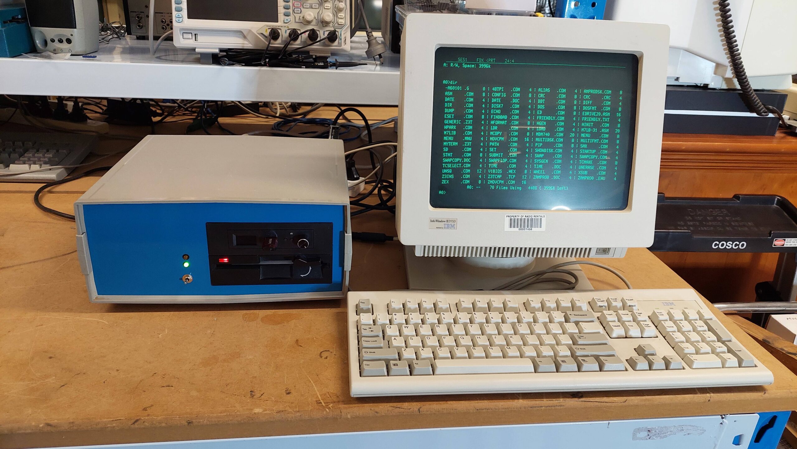
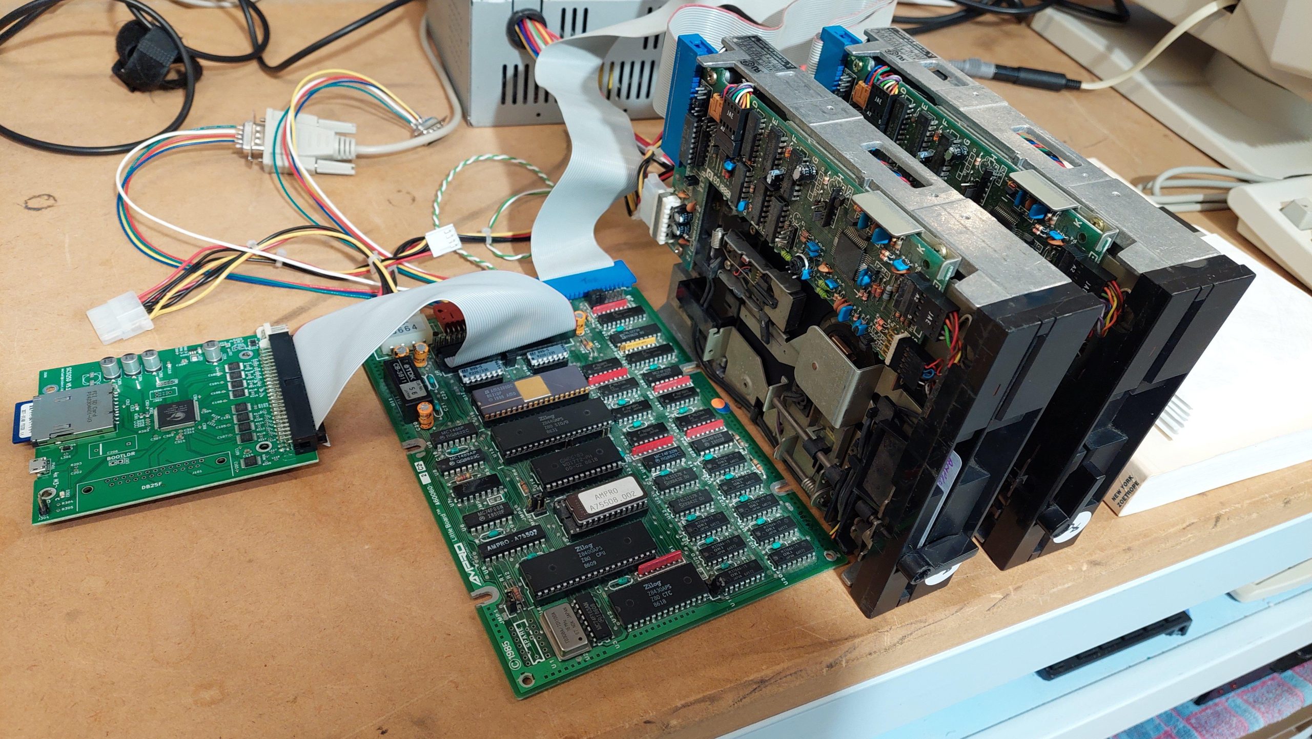
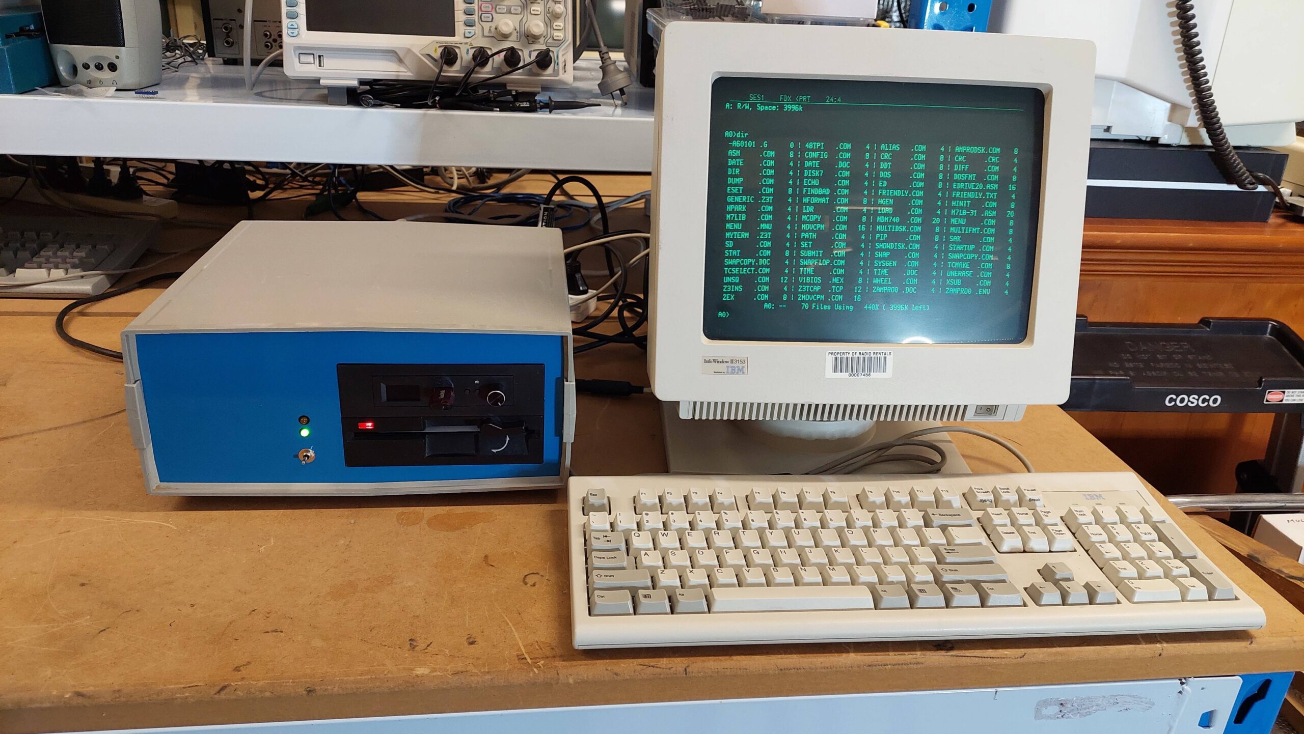
This is one of my current projects. It is based on the Ampro Little Board Plus which is a single board computer designed to be mounted on the back of a 5.25″ floppy disk drive.
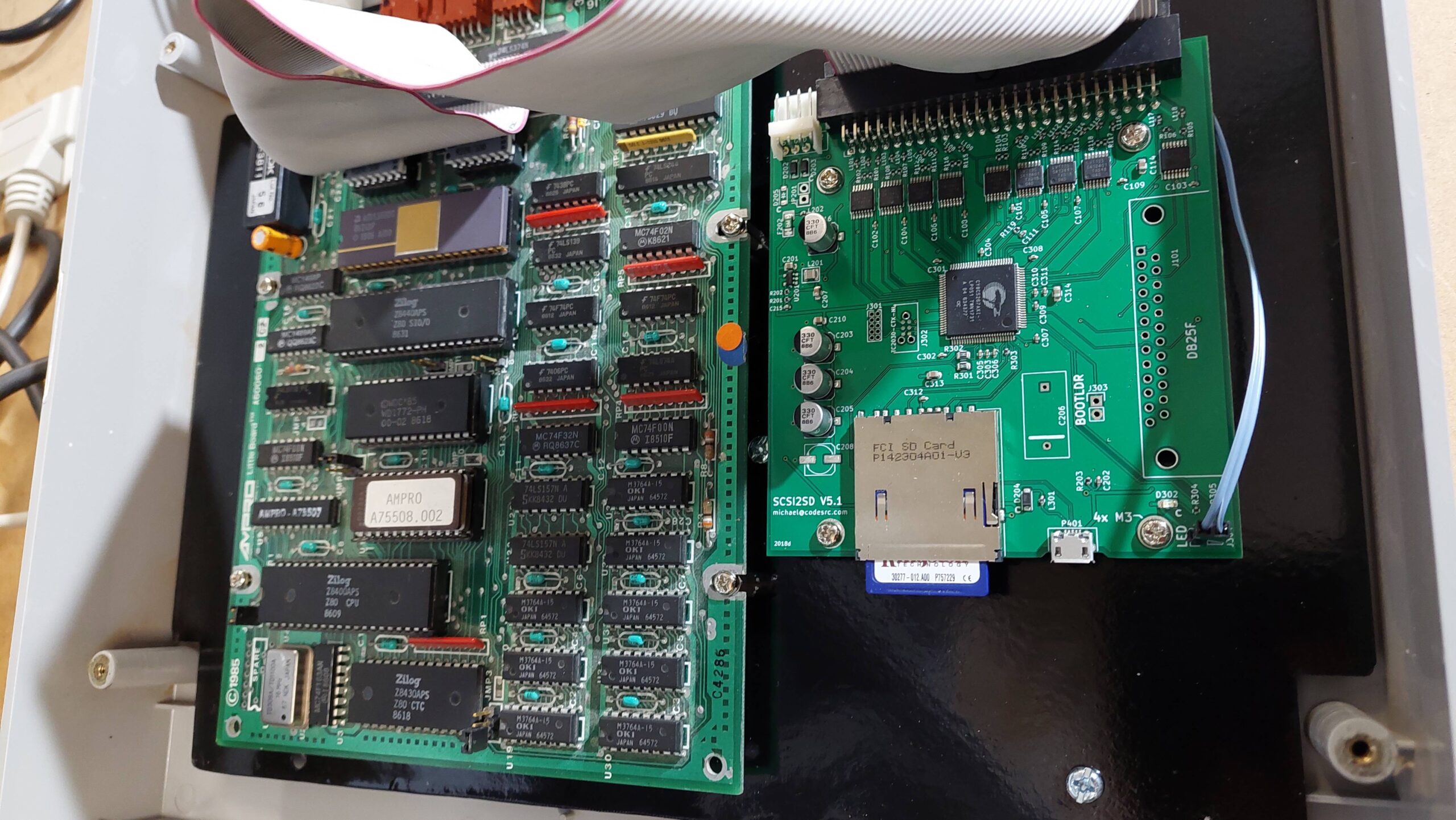
It uses a Z80 processor running at 4MHz and includes two serial ports, one parallel port, a floppy disk controller and a SCSI controller. It runs CP/M 2.2 and is happy to boot off a floppy or hard disk. I’ve added a SCSI2SD to emulate several 20MB hard disk drives.
The user interacts with the machine using a serial terminal.
I started off with the two 40 track Mitsubishi drives shown but have been using a gotek (with FlashFloppy) for the software load.
Currently, i’m loading up a whole bunch of software from images created using cpmtools. Eventually this will be mounted in an external drive enclosure.
This took me a bit longer than I expected because I didn’t read the instructions. CP/M needs to be configured to have some hard disk buffer space, otherwise the format fails mysteriously. I changed it from 60k to 56k. That allows room for the maximum 88MB of total disk storage.
The hformat program allowed for different controllers but after some experimenting I found success with the Seagate ST-225N hard disk.
+-----

Form                 5.25"/HH              Cylinders     615|     |     |

Capacity form/unform    21/   25 MB        Heads           4|     |     |

Seek time   / track  65.0/20.0 ms          Sector/track   17|     |     |

Controller           SCSI1 SINGLE-ENDED    Precompensation

Cache/Buffer               KB              Landing Zone      670

Data transfer rate          MB/S int       Bytes/Sector      512

                      1.500 MB/S ext ASYNC
I set up sd2scsi with 7 drives each with 615 x 4 x 17 = 41820 sectors of 512 bytes.
I used hinit (with burst mode) to set up 2 partitions on drive 0 and drive 1:
8192k
8192k
This needs to be done on every boot (really? yes) but an alias can be created:
alias

HINIT YD010 AF8192 AG8192, YD110 AF8192 AG8192,.

hardinit
then another alias that does this and swaps the drives over:
alias

HARDINIT; SWAP AF BG CH DI; STARTUP

HSTART
Startup can contain whatever is wanted, eg a menu program.
HSTART can be run on boot by adding at item 5 in the config program.
Copy the system track from the boot floppy to the hard disk using SYSGEN (watch out for the letter swapping).
Less than obvious (it’s in a separate section of the hard disk software manual right at the end) are instructions for autostart, noting HGEN in particular.:
When the system starts, it looks for a boot floppy. If it finds it, then it will boot from it. If it doesn’t find it, in about 10 seconds it will boot from the first hard disk partition. For some reason it keeps looking for a disk in the first floppy disk drive. If you give it one it stops but does nothing with the disk.
The Little Board was designed so that it could be mounted to a 5.25″ floppy disk drive. In keeping with this vibe, it uses a floppy disk drive power connector with just 12V and 5V; -12V for RS232 is generated on the board itself.
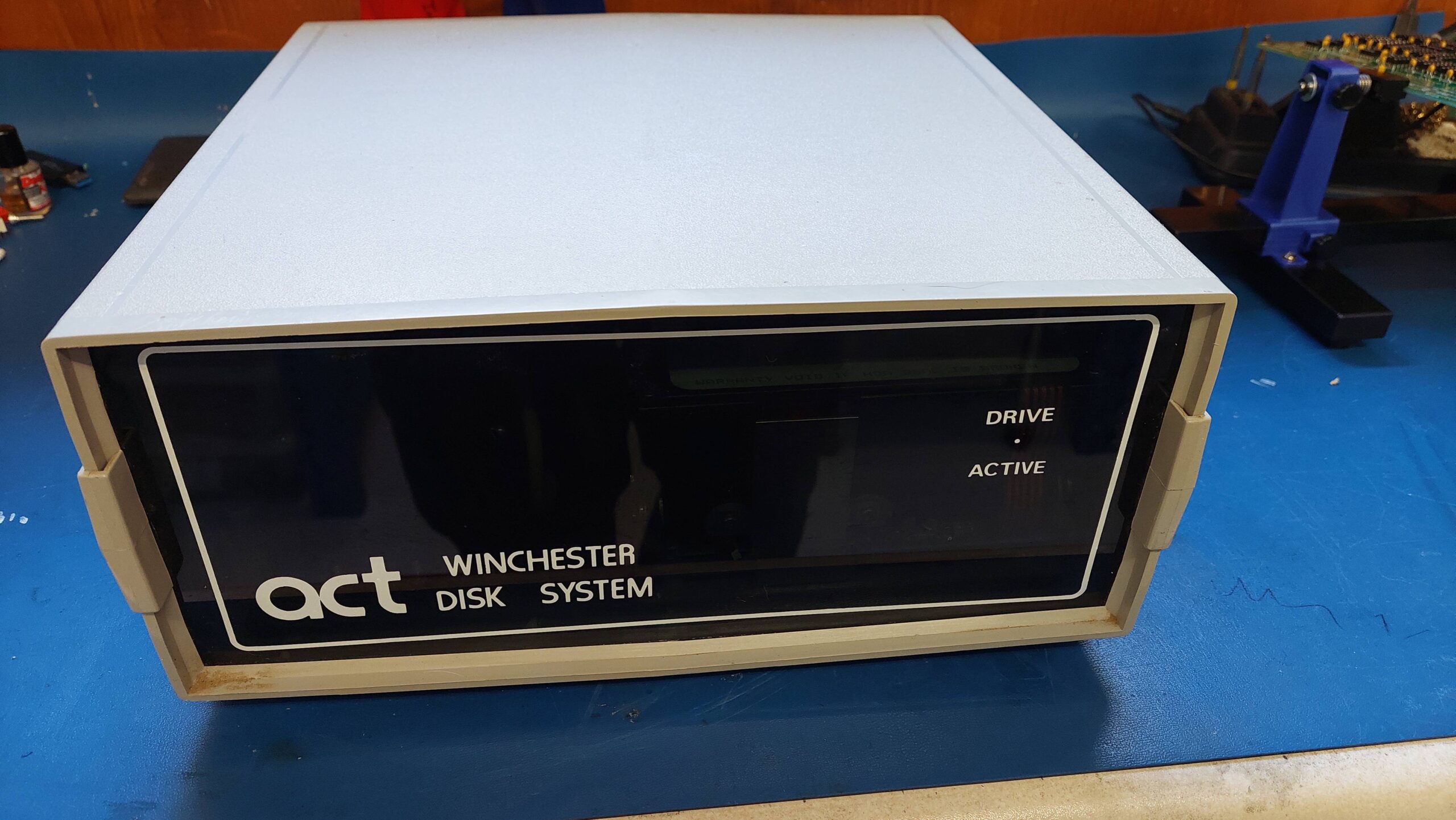
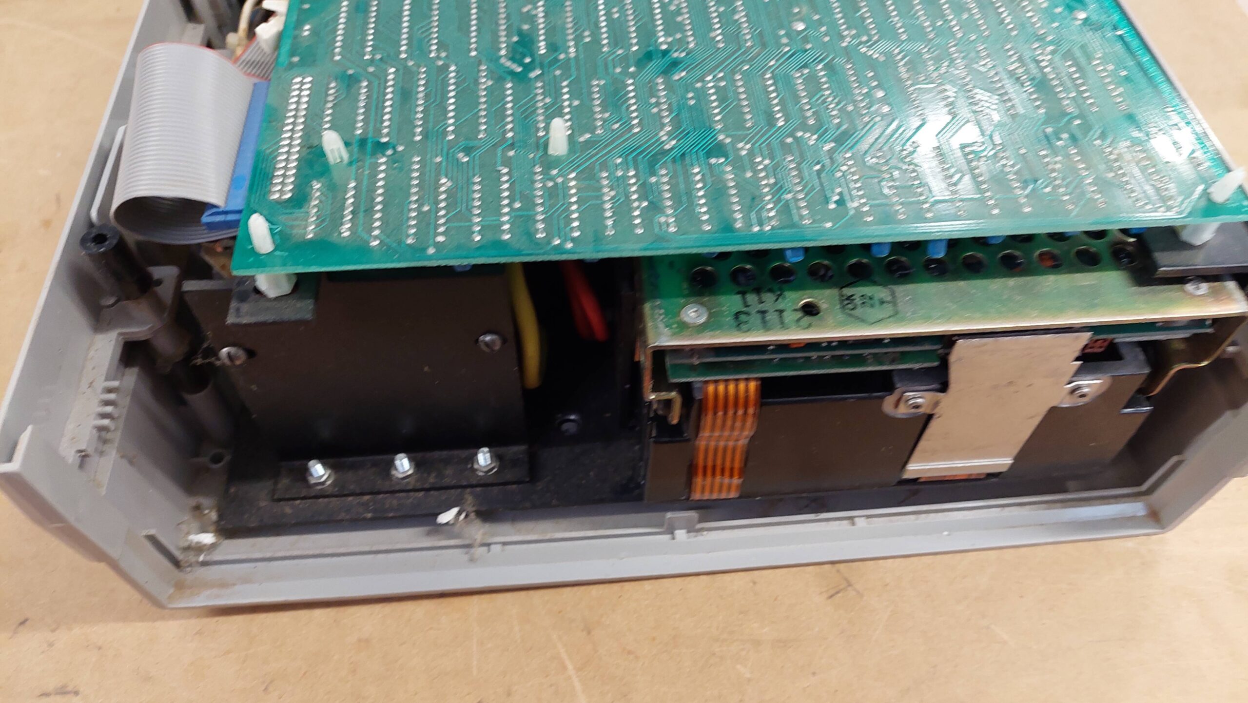
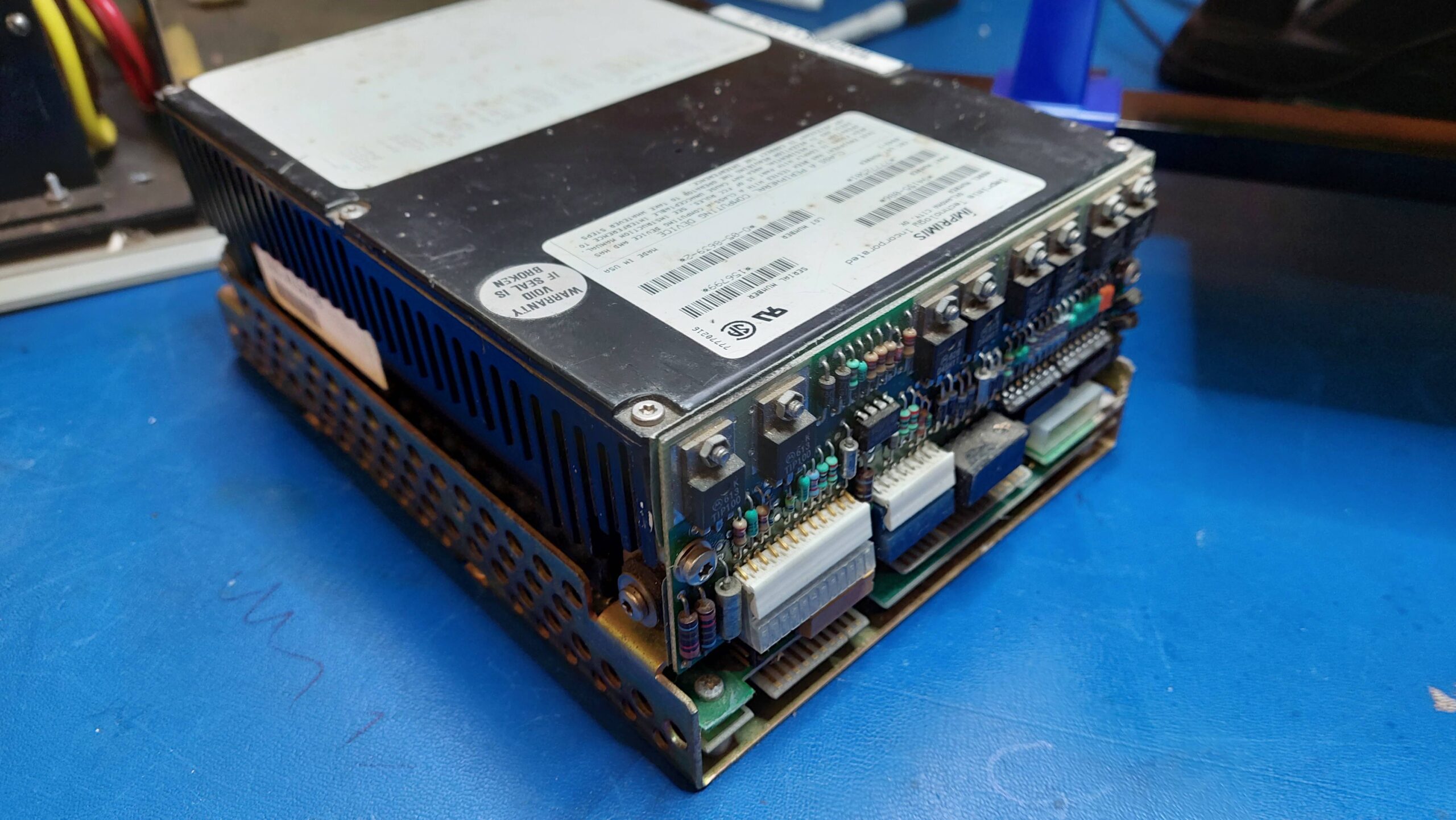
With this in mind, i thought that perhaps a disk drive enclosure could be a useful starting point. I had bought a hard disk in an external enclosure at a swap meet, but i was unable to find any information on the interface. I figured that the drive within would not be reliable in any case.
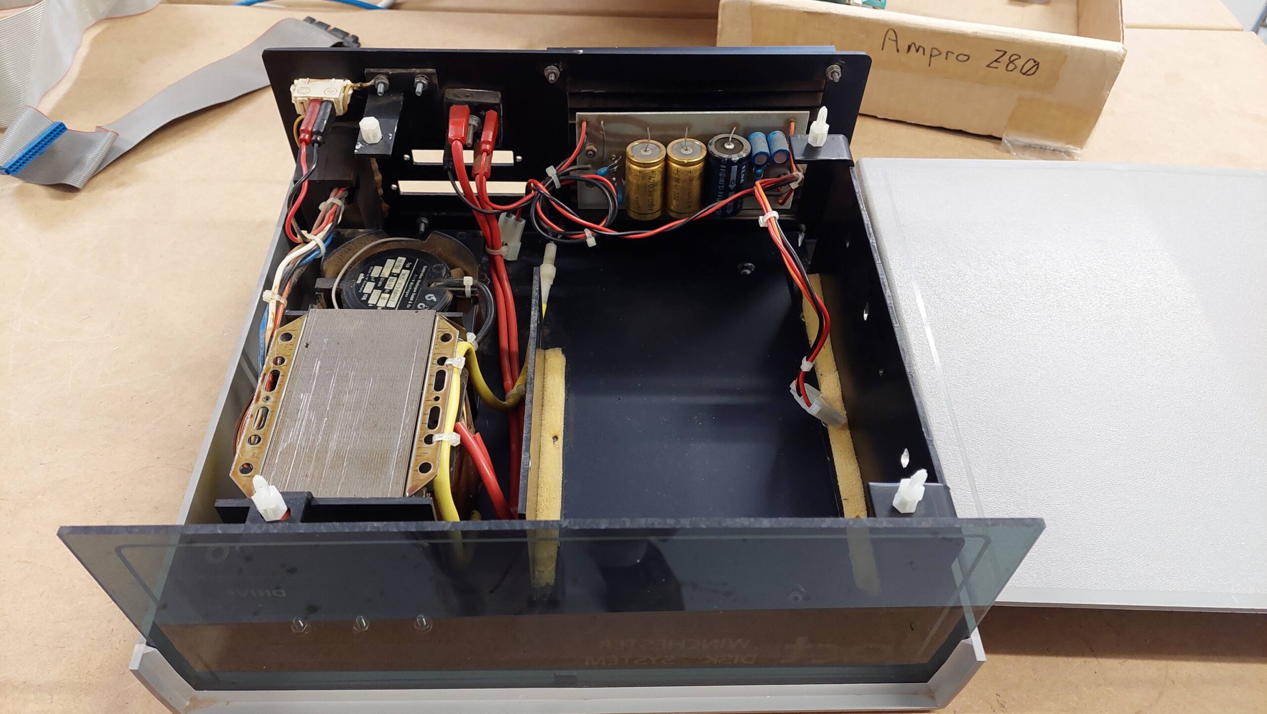
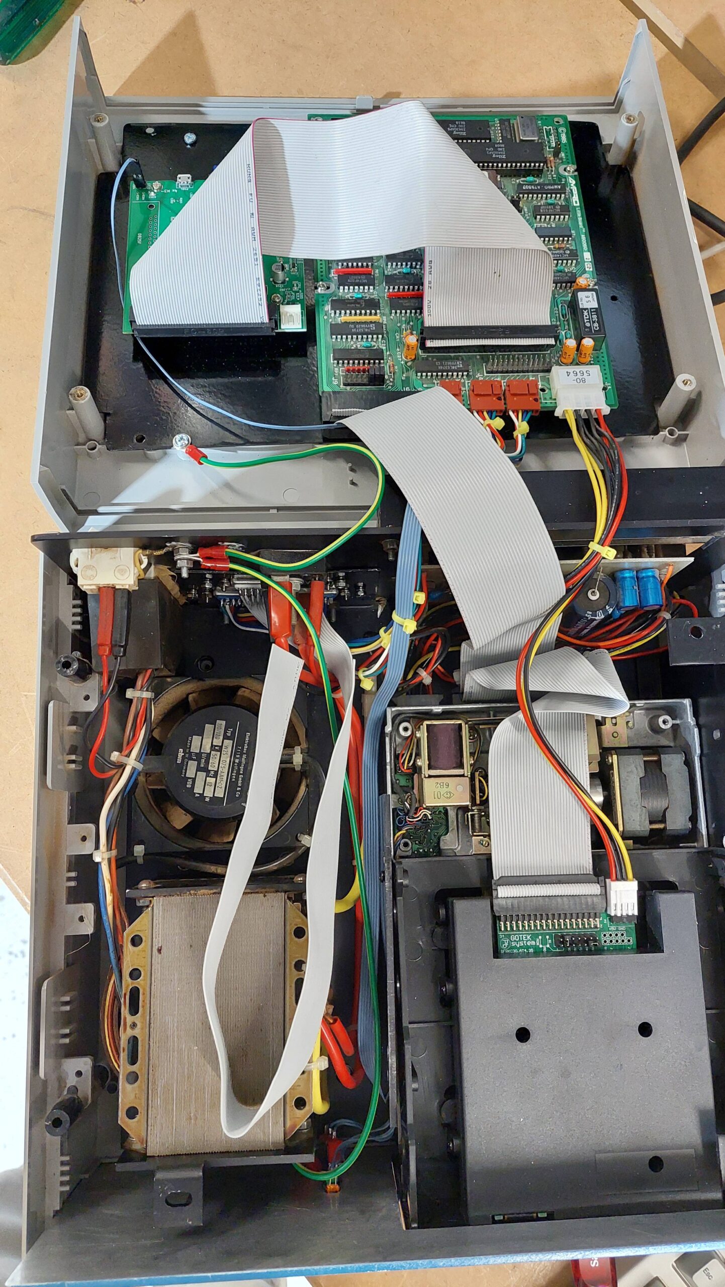
The enclosure has a heavy linear supply providing +5V and +12V. The drive itself is a full height 5.25″ drive, so there is sufficient accommodation for two half height floppy disk drives.
I figured that i could sequester unused parts, including the hard disk, just in case i wanted to return it to its original state.
I wanted to include a physical floppy disk drive, a gotek emulator, the Little Board, and a SCSI2SD card. If i mounted the Little Card to the floppy drive then it would have been underneath which would make it difficult to access the connectors.
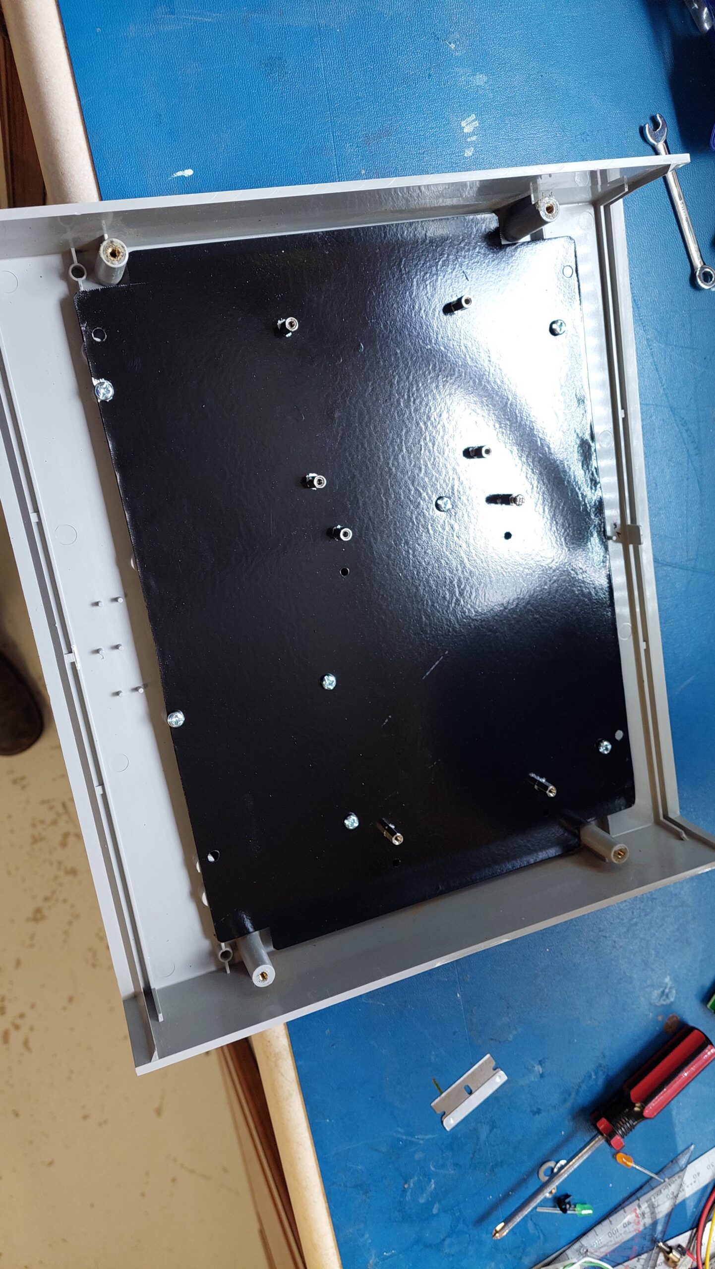
Instead, i created a “baseplate” to accommodate the Little Board and the SCSI2SD. I mounted the baseplate on the top cover.
I replaced the perspex front panel with a new aluminium panel with a cutout for the drives and holes for power and hard disk lights and a reset switch.
Both the front panel and the baseplate were earthed. I used metal standoffs and cleared paint so that they would ground the cards.
The front panel got a couple of coats of gloss Bermuda blue.
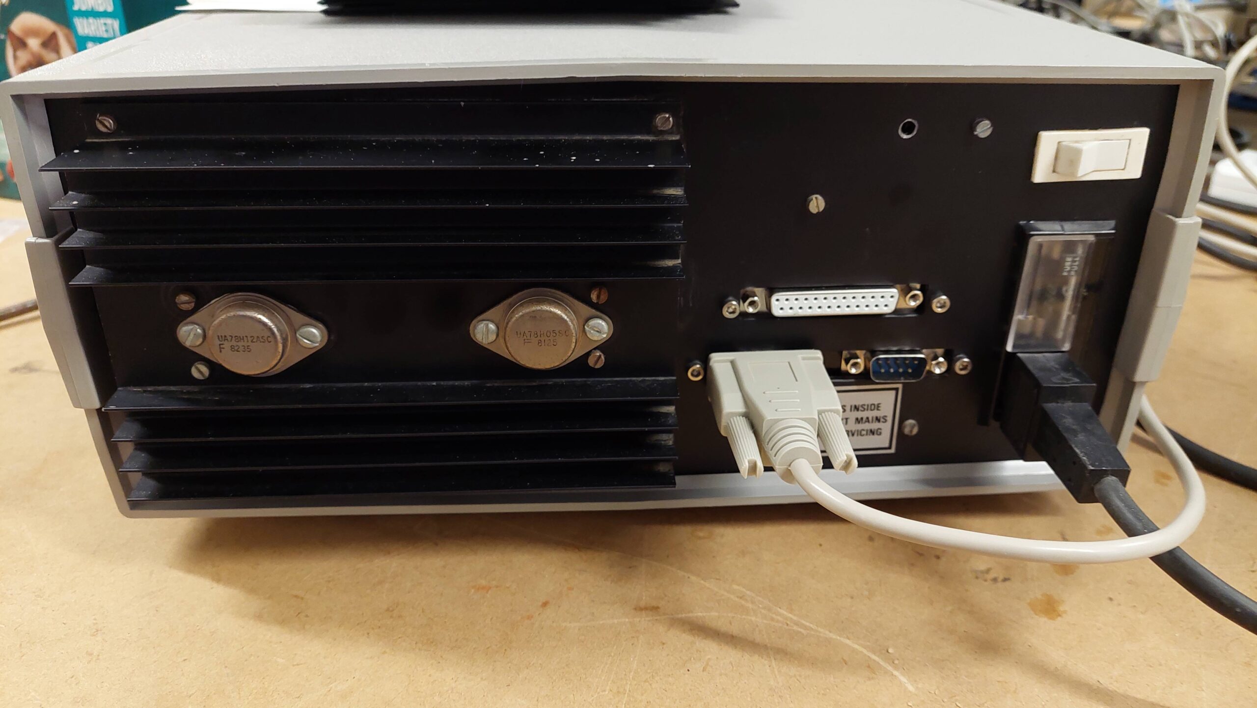
The enclosure had a couple of cutouts for connectors, which gave enough space for two 9 pin serial ports and the 25 pin printer port. I made up a custom panel to overlay the existing cutouts.