Pulsar 7500 Floppy Disk Drive

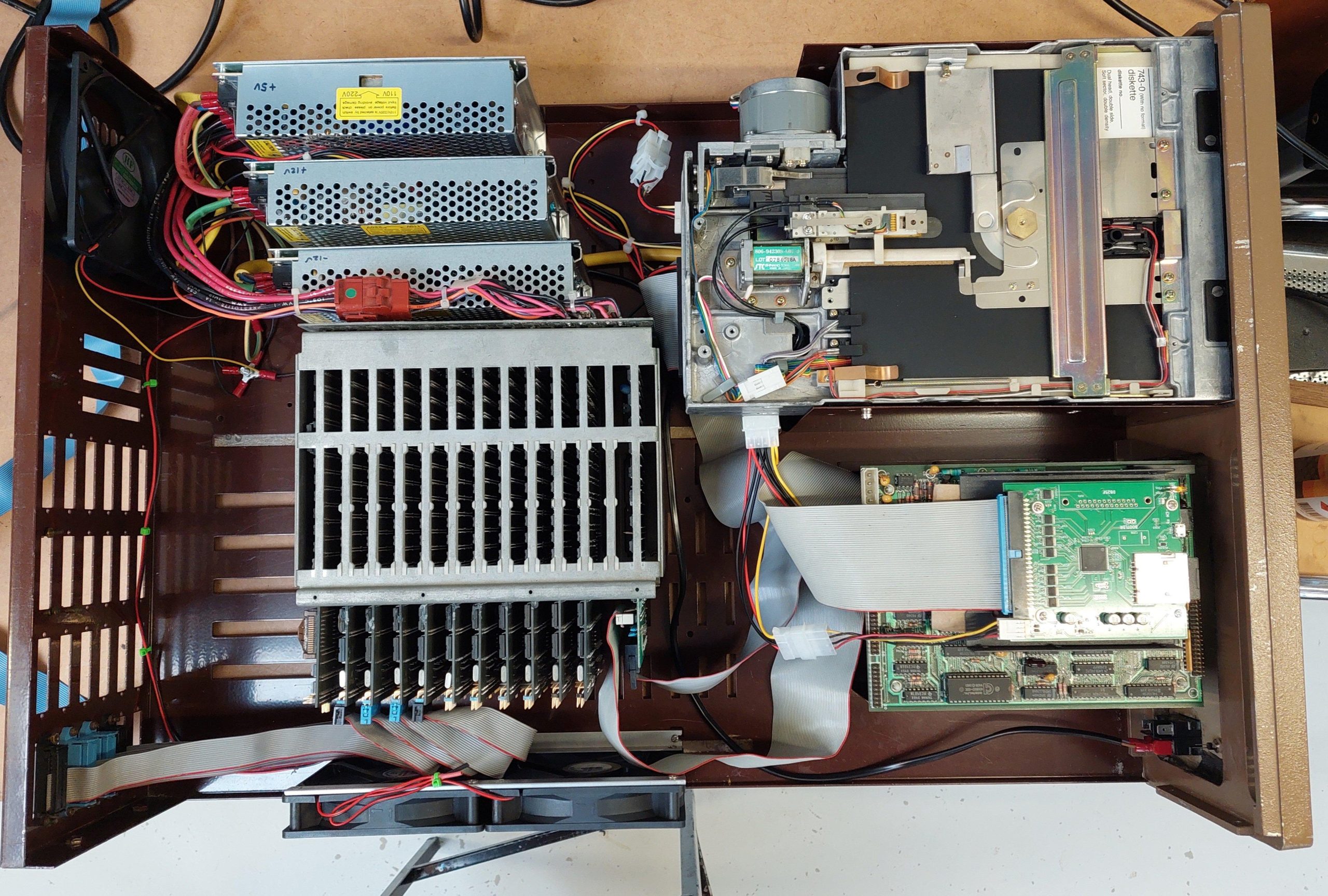
The 7500 system uses a 5.25” drive rather than an 8″. As it turns out, the floppy disk drive in this unit, Mitsubishi 4854-342, is intended as an 8″ replacement – it even claims to be a 77 track drive although i suspect it’s good for 80. 

https://retrocmp.de/fdd/mitsubi/m4854_i.htm

The 50 pin host interface is connected to the 34 pin drive interface via a simple adapter. All up, this means that the 8” images can be written to HD 5.25” disks.

Looking at the simple 50/34 adapter board, I suspect that the drive has a couple of signals that may not be present on a 5.25” interface – Ready and 2Sides. I imagine that 2Sides is always asserted because there is no way for a 5.25″ drive to know if a disk is single sided. 8″ drives can.

The drive was cleaned and lubricated and tested ok with Imagedisk.

8” Pin8” SIgnal5.25” Pin5.25” AdapterComments for Emulation with Gotek
2TG43_LNot used
4
6
8
102SIDES_L2REDWC_LNot driven by controller or gotek.  Pull down
12
14SIDESEL32SIDESEL
16
18HEADLOAD_L4Not Used
20INDEX_L8INDEX_L
22READY_L34DISKCHG_L
24
26DS010DS0
28DS112DS1
30DS214DS2
32DS36DS3
34DIRC_L18DIRC_L
36STEP_L20STEP_L
38WDATA_L22WDATA_L
40WGATE_L24WGATE_L
42TRACK0_L26TRACK0_L
44WRTPRT_L28WRTPRT_L
46RDATA_L30RDATA_L
48
50
16MOTORON

I wrote an HD floppy disk from 8″ disk image 8_257_02 (Pulsar Turbo V1.3 Master Configuration Sys 14 Config V24 Single User) using greaseweazle.

Pulsar 9000 Computer

Pulsar was an Australian computing company located in Melbourne, Victoria. They made STD cards and computings systems based on the STD bus and often using TurboDOS.

TurboDOS is a multiuser/multiprocessor operating system that can execute CP/M programs.

Eight Z80 processors and two 80186 processors share an 8″ floppy drive and a SASI/SCSI hard disk, supporting 9 concurrent users. Each Z80 user gets their own 64k in which to run CP/M-80 programs, while the lucky 186 user scores 256kB in which to run CP/M-86 programs.

The master board, a 80186 board, loads the operating system from disk and, once it is up, it transfers the operating system to each of the slave cards.

All the rack-mounted cards are bona fide eighties cards. The rack and the 8″ drive are also of the time. The re-construction is new. I was able to find only very scant details of the Pulsar 9000, but i did have a complete set of cards and some software handbooks. It looked like a project!

Swapping to 8″ System Drives

Initially i built the 68000 Cromix system using high density 5.25″ disk drives for the system drives. Having been able to install Cromix it was time to take the next step and add genuine 8″ drives.

The selected drives were Mitsubishi M2896-63 half height drives.

The 16FDC disk controller was designed primarily for Cromemco Persci drives. I don’t have of these drives and am unlikely to ever find any.

The 50 pin interface is quite different. I stumbled on this document by Martin Eberhard that examined in detail how to adapt the 16FDC to use Shugart SA800/850 drives.

I shamelessly used this very handy information to make an adapter cable for the Mitsubishi drives.

16FDC Pin16FDC SignalDrive PinDrive Signal
2Side_Select14Side_Select
4DS4_L32DS4_L
6N/C6Alternate I/O
8N/C8Alternate I/O
10Seek_Complete_L  
12Restore_L  
14Eject_L  
16N/C16Alternate I/O
18DS3_L30DS3_L
20Index_L20Index_L
22Ready_L22Ready_L
24Motor_On_L18Alternate I/O /Head_Load_L / Motor_Start_L
26DS1_L26DS1_L
28DS2_L28DS2_L
30N/C  
32N/C  
34DirC34Select (Direction)
36Step_L36Step_L
38Write_Data_L38Write_Data_L
40Write_Gate_L40Write_Gate_L
42Track_0_L42Track_0_L
44Write_Prot_L44Write_Prot_L
46Read_Data_L46Read_Data_L
48N/C48Not Used
50N/C50Not Used
  2Alternate I/O / Write Current Switch
  4Alternate I/O
  10Alternate I/O
  12Alternate I/O
  24Not Used

[Next time a drive is out, get the jumper settings.]

I reinstalled Cromix 20.09 on the 8″ disks using the same instructions as i had used previously.

8″ Disk Drive Unit

I had a badly deteriorated industrial computer chassis with accommodation for 2x 8” drives.  It also had a cutout for two 5.25” floppy drives.  I could have used it on an STD project, but I have another rack that I can use for that which is more compact and has an integrated power supply.

I figured that if i reduced the length of the chassis to get rid of some bulk, then it might make a good drive unit for the Cromix system above. 

It took a lot of mechanical work, but the result worked pretty well. I put a window in the top cover just so that the operations of the 8″ drives could be seen and enjoyed – not something i would have done with a vintage unit.

I added one more high density drive (Mitsubishi 4854) which is on the 5.25” cable but appears to the cromix to be another 8” drive. I had to make a small mod to the 16FDC board to route the pin 34 of the 5.25” interface (RDY) to pin 22 of the 8” drive interface.  This is because the high density 5.25” inch is treated as an 8” drive and Cromix expects a ready signal for those drives.

This particular Mitsubishi 4854 drive has a curious property whereby the reduced write current pin 2 has been disconnected – possibly because it was in a system which used pin 34 for a drive or side select.  The line is pulled up, but only when the terminator is in place.  That means this drive must carry the terminator because the line does have to be high.

Along the way I checked the alignment of the drive (which was good) but noticed that imagedisk could only make sense of the very first track on side 0.  Apparently this track is FM rather than MFM – probably for compatibility with the 16FDC ROM.

The Mitsubishi M4854 drive has a head solenoid.  The solenoid is probably unnecessary because the system seems to be ok with the drive spinning up on each access (this didn’t work with other high density drives or the 8″ drives). 

Currently, i use a gotek/flashfloppy in place of the 40 track 5.25″ boot drive. I start with an image of a 40 track boot disk and can then switch to any of the myriad of 8″ disk images from the GIT repository.

Drives/devices are arranged as follows:

 DriveMount PointSmallLargeUniform SmallUniform Large
0Gotekdasfdafdausfdaufda
18”dbsfdbfdbusfdbufdb
28”dcsfdcfdcusfdcufdc
35.25 80 Trackddsfddfddusfddufdd

I also expect to be able to use this unit with the Compupro/Jade CP/M machine. 

8085/86 Getting Started

This machine is a reconstruction of a hobbyist built machine from the early eighties. It came to me in pieces in amongst a lot of other gear, so it wasn’t obvious to me that there was a complete computer there at all.

I had already rediscovered a Cromemco based computer which used half a dozen of the 29 S-100 cards that i’d received. I also had a rack, some 8″ drives, and a lot of 8″ disks which i had previously imaged.

Many of the disks were labelled as being Jade, and there was indeed a JADE DD Floppy Disk Controller amongst the cards. There were many more disks that used the JADE format.

There was also a Versafloppy II Floppy Disk Controller card, for which there were also a number of disks.

These were all CP/M disks so i was looking for a 8080, 8085 or Z80 processor board. The candidates were a Cromemco SBC which wasn’t a great fit with CP/M or a CompuPro 8085/88 CPU card which would work.

I also expected there to be some I/O and a card for a boot ROM. And RAM of course. There weren’t a lot of clues from the cards themselves.

Fortunately there was a disk labelled “Jade System BIOS Development which contained some assembler files for the CP/M bios and the boot ROM. At this point, i ruled the Versafloppy II out.

The boot ROM code had some comments identifying key components (8251, 8255 and 8253) on a W/W card. Once i found the card with that combination of components, i realised that W/W stood for wire-wrap. It was a hand-crafted board. It also has a speech synthesiser chip!

Looking at the chassis, i could see that the wires dangling from the back panel married up with empty sockets on the board.

A little while later i realised that there a couple more ports which may belong to this unidentified card:

It has a real-time clock on it.

I had several memory cards that could potentially be used, but given that the CPU card is capable of addressing more than 64k, i started with an Intersystems 256KDR.

This card is probably overkill, and i may swap it out in the future.

I do have an EPROM card, but it is made for 2708 EPROMs which i can’t program at present – i would need a new programmer.

Instead, i built a new card using a modern S-100 prototype card.

These cards for the basis for the system.

Jade Double D FDC

The Jade Double D is notable for being an intelligent floppy disk controller. The onboard Western Digital FD1791 FDC chip is controlled by a Z80 processor. The CPU communicates with the DD through a 1kB window.

Although the card includes a processor and 2k of RAM it has no ROM. Instead, code must be injected by the CPU card. The code is embedded in the CPU boot ROM.

The boot code assumes that the window address must be set to F400. The jumpers were already correctly set.

This card supports 5.25″ drives on a 34 pin interface or 8″ drives on the 50 pin interface. Eventually i will use 8″ drives with this machine, but in the short term i just wanted to use a couple of goteks (with Flashfloppy).

The images that i wanted to use are from 8″ disks. These work fine in the gotek but because the gotek uses the 34 pin interface there were a couple of residual issues. There are a some signals expected by the boot ROM and the CP/M BIOS for the 8″ drives that are not on the 34 pin interface.

The first is the RDY signal which is supported by Flashfloppy on pin 34. This requires a link on the DD from pin 34 of the 34 pin interface to pin 22 of the 50 pin interface.

The second is that an 8″ drive can detect whether a disk is single or double-sided – the index hole is in a different location. For this, i added a switch to assert or negate the SIDES signal depending on which image i had loaded. I later copied all of the single sided disk images to double-sided disk images to make things a little simpler.

This card had a couple of hardware issues. The first was two shorted tantalums. The second was that, for whatever reason, two sockets had been butchered, and the chips soldered to the socket pins.

I replaced the sockets and devices.

Using HD 5.25″ FDDs as 8″ Drive Substitutes

High density 5.25″ disks have much the same capacity as 8″ double density disks, and they operate at the same data rate. A 5.25″ FDD typically has a few more tracks than an 8″ FDD.

This means that a floppy disk controller expecting to see an 8″ disk drive can potentially be fooled into working with an HD 5.25″ drive. This can be very handy if you don’t have an 8″ drive or if you want a more compact setup. This trick seems to work ok with a real HD drive or with a gotek/flashfloppy. 8″ disk images can be written to HD 5.25″ media without alteration using Greaseweazle, for example.

There are a few small issues. The first is the 8″ drive interface is usually 50 pins and the 5.25″ interface is usually 34 pins. The disk controller may have both interfaces (eg the Jade DD and the 16FDC) but not always (eg the Pulsar Little Big Board only has a 50 pin interface). If there is no 34 pin interface, then an adapter will be required. The 50 pin interfaces vary a bit, so a specific adapter may be required.

The second is that 8″ drives can detect whether a drive is single or double-sided and tell the host. The operating system driver may exploit this information (eg Jade DD CP/M) so there may need to be a way to fake this. For systems that use only single sided or only double-sided disks the signal can be tied appropriately otherwise a switch may be required – and if there are different drives in the system then it may be necessary to take the signal low through a diode from the drive select line.

Third is that 8″ drives typically produced a ready (RDY) signal. Without this signal, a host may just hang. This signal is available on many drives and can usually be setup on a gotek/flashfloppy but it may not be connected on the 34 pin interface. This can be overcome by connecting pin 34 on the 34 pin interface to the appropriate pin on the 50 pin interface.