Posts
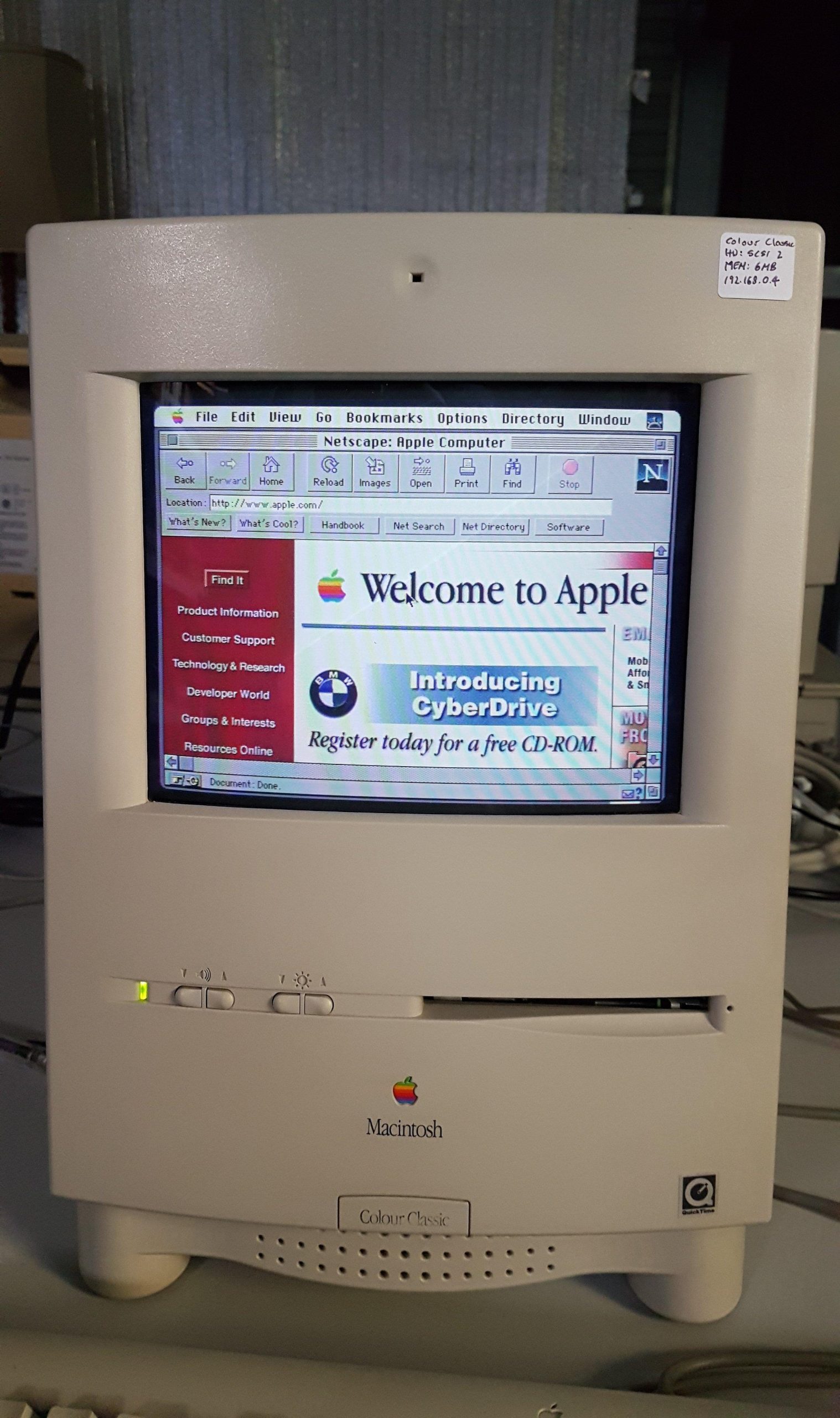
Macintosh Colour Classic
Macintosh Classic
This Macintosh Classic was given to me by my friends, Paul & Margaret, so it means just a little bit more to me than the average Classic.

These machines are somewhat notorious for leaking capacitors and batteries. The only other time that i worked on one of these machines, the corrosion was awful.
I started by opening up the machine for a look. I was happy to see that the battery had not leaked and that, although the logic board capacitors had leaked a little, the damage did not seem to be severe. The analog board seemed to be in good shape.


I gave the logic board a quick clean and then powered it on. I was greeted with a chequerboard.

At that point, i ordered some replacement caps. When they arrived, i carefully removed the old ones with hot air. With the old caps off, i could clean more thoroughly and then inspect the tracks around the capacitors.
Cleaning involved a good wash with PCB cleaner, removal of corrosion with vinegar and then several days with deoxit in stubborn spots.

I carefully scrapped away loose solder resist and cleaned up the copper beneath. A fault was clearly visible under C8. I made the connection using kynar at the source and destination pins (an address line to the ROM). I didn’t want to have a dodgy track repair under a component.
I tinned all the exposed traces and then replaced the capacitors with tantalums. The battery was replaced.

With the track repaired, the machine came to life!
This machine has a total of 4MB of memory. The original hard disk is going for the moment. The floppy disk is operating nicely so it may be a handy bridge machine for 800k disks.
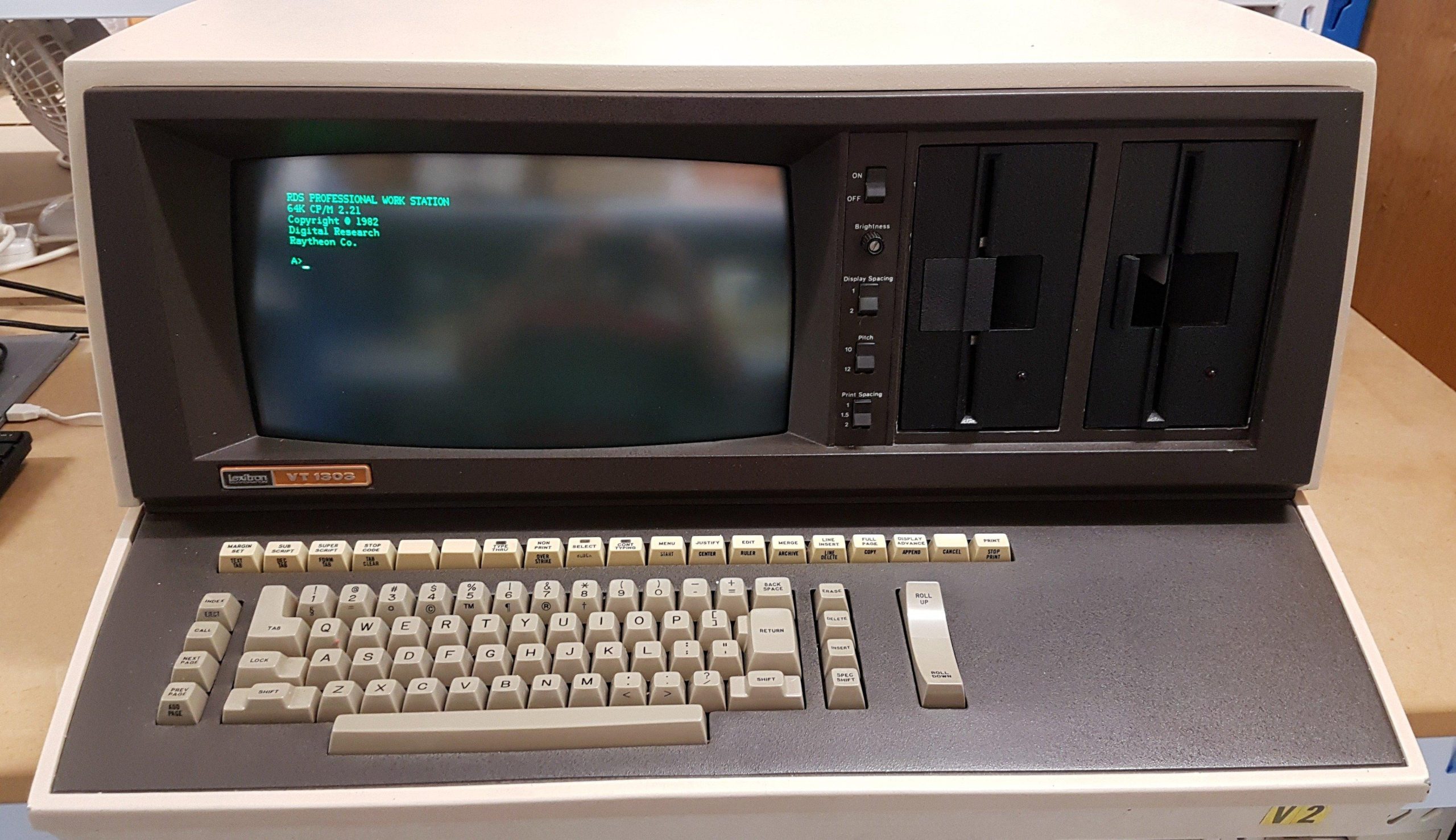
Lexitron VT1303
- Lexitron VT1303
- VT1303 Inspection
- VT1303 Power & Fault Finding
- VT1303 Backing Up Disks
- VT1303 Keyboard Fix
- VT1303 Printer
- VT1303 CP/M
- VT1303 Transferring CP/M Files
- VT1303 Screen Cataracts
- VT202/1303 Keyboard Fix Revisited
- VT202/1303 Comms Card & Kermit
- VT202/1303 BDS-C Compiler
It was never my intention to buy this machine. I drove out to Lewiston (just north of Adelaide) to collect another purchase, and the seller asked if i would be interested in this mammoth. It had apparently come from a South Australian government department, but had been subsequently used by the seller and his family for several years during the eighties.

I did some quick research and found that it was a word processor – not really my cup of tea. In the end, i bought it for about the value of the two drives. It also came with a daisy wheel printer, a long and heavy-duty printer cable, a couple of manuals and some beaten up looking disks. The screen looked like it had some kind of disease, which was later identified as CRT cataracts.

I was happy to find that the drives were Shugart SA400 drives because these are the first really successful 5.25″ drives.
Backing up the disks was an exercise in itself, but once done, i set the machine to work. I replaced a shorted tantalum and gave the drives some love. I started the machine up and, surprisingly, the machine booted into its word processing program.
Mild joy was short-lived: the keyboard did not work, and it was the microcontroller that had failed. At this point i should have pulled the drives and some other spares and sent it off to the recyclers. Instead, i built a teensy based replacement for the microcontroller and reverse engineered the keyboard. This act of madness yielded a system that was close enough to demonstrate the machine as a word processor.
Along the way, i had picked up hints of CP/M being available for this machine. I periodically did google searches to see if there might be some images kicking around and to my surprise about 3 years later they appeared on archive.org (thanks to the person who did that – dasher perhaps).
Once written, with some help from an Adelaide Retro Computing Group member (thanks Mick S), the machine was able to boot to CP/M and take on a new life as a computer.
If the success of a vintage computing purchase is measured by the hours endured to get it working (the primary entertainment value), then this machine has certainly delivered.
For a little history of Lexitron see the video here:
VT1303 Inspection
This machine is not easy to manoeuvre; it takes two people to lift it. And this is with a switch mode power supply.

The screen looked to have deteriorated. There were what looks like mould spots all over it. I thought that the CRT may have been broken, but casting light on it showed the spots were not on the phosphorous but just below the surface of the glass.
It looked like it may have been under a protective layer. A check on the web confirmed that this is a case of CRT cataracts where the adhesive holding protection screen on deteriorates. It’s not terminal; it can be repaired.
The owner showed me how to take the top cover off – just two screws at the sides that need to be loosened.
Inside there is a long baseboard with a terminal block at one end and a passive backplane at the other. It was not clear to me whether each of the 7 cards had to be in a particular location.
The primary power supply is located on the right and the secondary low voltage supply, providing regulation of various voltages, is on the left.
The backplane did not appear to correspond to any bus that i had seen or read about.

The CRT is at the front left and is driven by the board at the far left of the card cage. The drives are mounted in a frame at the right.


The primary supply is a switching unit. It provides several unregulated outputs to the secondary power supply to create all the required voltages for the backplane and the drives. I could not see any of the infamous Rifa line filter capacitors. All other caps looked fine.
The floppy drives were removed, cleaned, lubricated and refitted. The thumb screws up the top retain the drives.
The main processor is an 8085. The card doesn’t have a lot on it but includes the printer interface, the keyboard interface, and the boot ROM. I don’t have any schematics or technical documents, so exactly how this card works is a bit of a mystery.
The date codes include 1981 so i’m thinking this was quite a late unit. There seems to be a lot of kynar for a design that i’d expect to be a few years old.

The DRAM card provides 96kB of memory so it must have some form of windowing going on. It uses 16kb DRAM chips which worried me a bit because they are often unreliable.

There are two floppy disk controller cards, which is unusual; normally a controller card would look after multiple drives. This was either very inefficient, or there was some scheme that allowed concurrent reads and writes.
There is a switch on each board near the 34 pin connector that sets the controller for Drive 0 or Drive 1.


There’s a character ROM at the top of Video Card 2. Character memory on the right of it: 6x256x4bit SRAM. That doesn’t seem like enough for a 24 x 80 display, so something else must be going on.


The only I/O that i could see was the printer port. No serial port is sad. (See VT202/1303 Comms Card & Kermit.)
Both the printer and the computer have 110V rating plates but the seller assured me that they had always run both units from 240V and the accompanying power leads certainly supported that proposition.
I thought that the supplies had almost certainly been converted, but I didn’t want to leave it to chance. I checked each unit and went looking for some evidence of the conversions. There is a wire on the power supply which has been moved from 100V to 200V.
The keyboard is secured by two screws underneath the unit, and the board is screwed to the surround. It uses a D8748 microcontroller.

All up, the machine struck me as being in pretty good shape. Sure, it’s just a word processor, but underneath it’s a computer looking for an operating system.
VT1303 Power & Fault Finding
I wasn’t particularly vested in this machine but, i wanted to see if there was life and if so how much life.
I turned on the machine using the circuit breakers at the rear of the machine. These felt a bit clunky but gave a satisfying click and the fans came to life with quite a lot of noise.
The drive lights flashed regularly, as if beckoning me to pop in the boot disk. I answered that call, but there was no attempt to read the disk.
I still had the unit open, and I could see an LED on the power supply flashing with the drive LEDs, so I figured it was probably a power fault. The CRT wouldn’t switch on.
I pulled all the cards from the rack (except the CRT supply which was a bit tricky) and the supply came up fine – solid LED. This prompted me to measure all the power supply lines and work out which supplies go where, including the computer bus.
The CRT still wouldn’t switch on, but I thought that it might need one of the cards that I’d removed. (The front panel switch is wired via the keyboard, as it turns out.)
Replacing the cards and connectors progressively went well until I connected the keyboard.
I checked which “pins” on the processor board edge connector provided power, –5V and 15V, and found that the keyboard did indeed have a short from 15V to ground. I cut a track to narrow it down. There was a tantalum on the remaining piece so, I took a wild guess that it would the cause. It was. I replaced it and made the cut track good.
After that, the unit fired up. The screen turned on, and the unit requested a boot disk. I gave it the only one that I had, and it booted.
Unfortunately, it wasn’t picking up anything that I typed. That led me back to the keyboard.
The keyboard is a Cortron unit. The company still exists and still makes keyboards, but I can’t see them lending much support.
The unit is almost certainly a custom unit made for lexitron. I was able to find some documentation for another computer that described how the cortron keyboards worked. I also had a good poke around the board. The working description for the other keyboard seemed to accord with what I could see on this unit.
The keys use contactless magnetic cores. When they are pressed, a pulse can be transmitted from one winding to another.
It’s all controlled from a microcontroller. The switches seem to be arranged in a 10 x 10 grid. The microcontroller addresses the array via two decimal decoders. I expect there must be a sense line back – I need to find that. The micro controller presents a byte to the host processor reflecting the key that’s been pressed or released. I imagine there’s some debouncing, and they must have done something about “shift”.
The keyboard also presents the state of the front panel switches. A mux routes either the keystroke or the switch state to the 8085 board depending on a select (address line) from the 8085 board. I suspect that the processor sends a “come and get it” strobe (maybe an interrupt) when a key press is detected.
The keyboard also has status LEDs (eg caps lock) and those are written by the 8085 board to a register on the keyboard. Ie the keyboard seems to just be a peripheral device on the 8085 bus rather than be accessed via, say, a serial port.
The bad news is that I could see no strobes. The micro controller looks dead to the world, although it is happily clocking. It is almost as if it has lost its program. That’s a real problem because I doubt that I’m going to be able to find that ROM binary. It is a UV erasable part rather than a mask program – there must be some kind of finite life.
This is going to be a bit of a problem to remediate. I don’t fancy writing that code using the original processor – it was probably in assembler.
At this point the sensible thing to do was to say, “well i tried” and then grab the drives and the RAM and chuck the rest into recycling. I put it down for a while before deciding that i could make a replacement based on a teensy board using the Arduino development environment. This board is vastly more powerful than the microcontroller, so i’d be able to work in c.
There are two pieces to be solved:
- the protocol and character coding (maybe ASCII) to the 8085 board
- how to detect keystrokes
This was a genuine case of suck it and see, and i knew it would be time-consuming. I decided to park the project until i could find a way to duplicate disks. In 2019, i don’t think greaseweazle had entered my conciousness.


VT1303 Backing Up Disks
The system came with a box of what looked to be well-worn disks. I had found no other disks online so as far as i knew, these disks, or copies of them, were the only disks that would boot up this machine.
I have one boot disk and a few data disks. They also seem to work in the machine.

I cleaned up the drives, and they seemed to work ok except for one quirk: they will only read data disks from the drive that is used to boot the machine. I’ll have to think about what that means – perhaps an addressing issue – or perhaps there’s a command required to change the current drive.
I’m pretty sure I’ve tried both drives with both controllers and with both controllers as drive 1. It’s another mystery, but I can’t mess with the disks too much until they are copied.
As far as I can tell, the machine makes no provision for copying disks. A bit of an oversight, I think. Surely there is, but without a keyboard I have no way of exploring anyway.
The disk drives are Shugart SA-400 units. They are single sided and have only 35 tracks. We’re peering back to a 1976 design here.
As I understand it from the manuals, they are single density disks (which turned out to be wrong) with 10 sectors per track. Unfortunately, single density really means that the coding is different. FM instead of MFM used for double density. The drives don’t care about the coding – the decoding is done on the floppy disk controller.
The disk controller cards use western digital FD1791B disk formatter/controller ICs, which is a fairly common family. Between the industry popularity of the shugarts, and the western digital disk controllers, i expected the formats to have a lot in common with other formats. I was dreaming.
There is a reasonable chance that ImageDisk could read the disks on an IBM machine if I was using a disk controller that supports single density. I don’t have one. It’s worth pursuing though because some other old machines also use FM anyway.
I purchased a relatively cheap Goldstar Prime 3b card which was rumoured to support FM, but i had no success with the card and Imagedisk.
Next was an Adaptec SCSI card which is also a floppy drive controller and is known to support FM. Fail. I tried another Adaptec card well known for supporting single density: Adaptec AHA-1542B. Fail. I concluded that it wasn’t FM coded.
I thought perhaps it might use some other variation. The Lexiton floppy disk cards are, after all, custom cards.
That really left me with very few options. Perhaps some custom hardware that might do the job – a catweazle card or a kyroflux – but they are hard to come by, expensive, and there was no guarantee of success. Either greaseweazle (and fluxengine) was not available in 2018 or it had escaped my attention. I put the job on hold.
My floppy disk skills have come a long way since 2018. These are double density disks but with a unique coding. The coding is built into the floppy disk controller cards. The disks can be read and written with greasweazle, but they cannot (at present) be decoded into recognizable sectors.
In early 2019, i noticed an isa card on a popular auction site, with a vague description, that was called a copy card. Being priced moderately, being located in Australia, and noting that it had what looked like a floppy disk edge connector, I thought it was worth making an enquiry. The seller was kind enough to send me some scanned pages from the manual, and it did sound remarkably like it could do a low level floppy disk copy. It sounded like it may have been a clone of the old CopyIIPC hardware.
It works by taking over the floppy drive data signal. The floppy drive cable is routed from the controller to the copy card and then on to the drives. It has quite a good little manual (no doubt inspired by the original) and the copy program has a few options to play with. It’s really made for copying tricky games disks but claimed to also be able to copy other formats such as apple and Atari. The irony of a copy card and its software being cloned was not lost on me.

I popped it into my PC XT. Initially i had no success with the lexitron disks, but I tried an apple ii disk and although it wouldn’t boot it did give a catalogue listing back on the Lingo Apple II clone which was encouraging.
I tried all the options, and found that with track length matching, and weak sectors turned on, I could get a Lexitron disk that would sometimes boot. I made a few more attempts and got some disks that seemed to boot every time. That doesn’t mean that they’re error free, but at least I could work on the Lexitron without putting further wear on that original disk.
VT1303 Keyboard Fix
I knew this would be a long haul, because i had no technical documentation and my c was very rusty. Without the user manuals, it would have been impossible.
Teensy++ 2.0
The Teensy+ 2.0 is often used for keyboard projects. It is about the same size as the microcontroller and has sufficient I/O to cover it.
It has a lot more computing horsepower than the microcontroller, so I don’t have to do a great coding job.
It is compatible with the Arduino IDE.
Reverse engineering
I was doing this in 2019. In Jan 2025 i got access to a working keyboard which confirmed some things and contradicted others. I’ve put updates in [] brackets.
I spent many hours trying to get the basics of the circuits on both the keyboard and the microprocessor board. I needed pretty much the whole keyboard circuit and some of the microprocessor circuit.
I worked from both sides of the interface. Both boards use 74 series logic, so there were a lot of connections to trace!!
With a 25 pin interface, I was guessing it was parallel. [Yes]
The front panel switches come in through the keyboard.
The keyboard has LEDs, so there was a pretty good chance that the interface was bidirectional. [Yes]
There is also a speaker in the keyboard, maybe for keyboard press feedback or for a bell. [Both yes]
The keyboard has a register for receiving data from the microprocessor board. There is a write line from the microprocessor board for the register. The LEDs are not controlled directly by the register. It is read by the microcontroller. Perhaps it has an interrupt. {Yes, although i didn’t use it as such]
It has two 4 bit muxes that are used to read from either the front panel switch states or from an 8 bit port on the microprocessor. There is a read line and a select signal from the microprocessor board for the muxes. [There are a couple of other status lines indicating key down and autorepeat.]
There are two strobes from the uC that are ORed and sent to the uP board. Both operate the buzzer but one is fixed volume and the other is adjustable with a pot. If both are asserted, there is no sound. Some of this I only worked out after I started trying some code. [The two lines are coded for 3 functions.]
On the uP board, the strobe sets a flip-flop which I expect is cleared by an interrupt routine.
The front panel switches work without uC software.
I have created a rough schematic of the keyboard.
Based on this i made up a plug-in replacement for the microcontroller.


A replacement with a USB port proved to be quite handy for other purposes. I recorded the port assignments etc in the source file for the software.
Keyboard Scanner
This is an unusual keyboard. Each key has a small ferrite core transformer which is saturated by a magnet when the key is unpressed. When a key is pressed, the ferrite core can pass a pulse from one side to the other.
The keyboard has 10 stimulation lines and 8 detection lines for a total of 80 keys. There is a shift key and a special shift key to generate more characters – 240 in principle – or even 320 if both were used.
There seems to be no reason why the scanner can’t happily detect all the keys that are pressed at any time.
Of course, any one time is one complete scan of the keyboard. I was thinking that somewhere between 50 and 100ms would be acceptable. Nobody is going to do any serious typing on this old machine. That gives about 1ms per key. [This turned out to be a bad idea. It’s too easy to miss the register writes. It now checks one key and then checks whether the register has been written.]
Generating characters
I wrote a sketch to enter a byte which would be transmitted once to the uP board. I used a scope to watch what was going on.
Part of this was discovering the timing for the data and the strobe. I could see the read in response to the strobe which is about 100us after the strobe.
The uP board seems to check the state of the strobe so it’s not just about the leading edge. Keeping it down for too long gives repeat characters.
I went through all 256 values to see what each does. Some were obvious; others less so. They certainly aren’t ASCII. The highest bit seemed to indicate shift.
The standard characters were easy to detect, but the function keys were very challenging. There is a lot of guessing involved. Trial and error. It would be impossible without the manual.
[It worked remarkably well, but my timings were out by a mile.]
Scanning the keyboard
Having bit 3 of the scan register asserted prevents the uP card from recognising characters transmitted using the code above. I could not work out why. [This line indicates that a key is down and is fed into the status register. If the 8085 software doesn’t see it, then it thinks the key is up.]
All the scan lines are driven from one register. 4 to set the stimulation line. 3 to set the sense line. 1 to generate a pulse. Timings were unknown but i was hoping it could be done in less than a millisecond. [A few microseconds works. The actual keyboard has the pulse low for about 50us and high for about 12us.]
The secondary pulse was quite short. About 100ns but the stimulation circuit needs to reload – there’s a capacitor that provides a small reservoir of charge and after that the current falls back to the DC level.
The pulse is about 500mV peak. The comparator inputs are set pretty close (about 15mV) so it shouldn’t have taken much to get a logic pulse. I couldn’t get one. I couldn’t provoke the comparator to ever go low so concluded that the LM319N was faulty.
A replacement LM319N did the trick. Keystrokes were recognised easily and within a 1us, I found there were false alarms, so I set it up to scan several times and need multiple hits to recognise a keystroke.
[I realised just recently that there is a uC output, pin 21, that affects the comparator threshold. It is normally high but goes low when a key is released. I suspect it provides some hysteresis. I’m not using it at the moment.]
I messed around with the dwell on each key to make sure I didn’t get multiple characters and I didn’t miss any keystrokes. I added code to work with shift keys and to auto-repeat.
Once the keystrokes were working, it was easy enough to collect the scan codes for each key.
Mapping Keys
Determining the key mapping without a working keyboard was quite an exercise, and I got remarkably close considering i had no understanding of the underlying protocol. [A working keyboard resolved the last of the protocol and mapping issues.]

And with this i had a working system with a pretty awful looking screen and a new USB interface!
VT1303 Printer

The Lexitron VT1303 came with a Raytheon RDS-345 daisy wheel printer. Although badged as Raytheon, it was manufactured by Qume. The model number is Sprint <TBC>. This is a very large and heavy unit.
The connection is parallel and is made with a very long 50 way cable. The connectors are centronics style, but the 50 pins are more reminiscent of SCSI than a parallel interface which is usually 36.
The printer came with some daisy wheels and printer ribbons.
It was definitely non-functional; the carriage and ribbon belts had both disintegrated. The platen knob was broken. There was also a lot of corrosion.
I was surprised to find that i could buy the carriage belt fairly easily – i would just need to cut it to length. The ribbon belt, which is very small, required a little crafting. The belt could only be replaced with a comprehensive tear down.
I couldn’t find a service manual for this printer, but i did find one for a similar Qume printer.
Replacing them required a fairly comprehensive tear down. There was also a lot of corrosion. This meant taking the print head off the rails etc which was going to trash the existing alignment and that realignment is quite tricky – it requires a bespoke alignment jig, for example. I was going to have to wing it.
I gave everything a good clean as i disassembled it and removed all the rust as best i could.
The belt was relatively easy to replace.

The ribbon belt is much smaller and is continuousbut the pitch is the same as the carriage belt. I cut the belt to width and then spliced it. It’s not perfect, but i don’t think it needs to be.


I put it all back together again and tried to work out how the relative position of the print head to the platen was set.
My first attempt to align it was a dismal failure. As it printed, the daisywheel didn’t spin freely and some of the arms went flying in all directions.
My second attempt was much better. This thing is awesome to watch. It spins the wheel very quickly to tee up the right character and then hits it with a little solenoid operated hammer.
The ribbons had all dried out, but i applied a little wd40 to one, and it was good enough to get some printing happening. I made some additional small adjustments to get characters completely printers – not missing the top or the bottom.


VT1303 CP/M
The system looks like it could support CP/M and i think i’d seen mention of it somewhere on the web, but i certainly could not find disk images.
I google “Lexitron” regularly just to see if any new material has been added. In June 2021, i was surprised to find that some disk images had been uploaded to archive.org. That person really did me a huge favour.
https://archive.org/download/lexitron-vt-disks
Amongst the images were some CP/M disks. Just one problem – they were in Kyroflux format. By 2021 Greaseweazle was certainly available and it did have Kyroflux support. I’m not sure why i didn’t head straight down that path – it’s lost in the annals of time.
In any case, it turned out that an Adelaide Retro Computer Group member, Mick S, had a Kyroflux, and he was kind enough to write all the images to floppy disk for me.
It was awesome to find that some of the disks worked:
- CP/M system disk with assembler and debugger
- Supercalc
- DBase II
Unfortunately, I had no joy with mbasic or wordstar. The wordstar disk seemed ok, but the binary just terminated with no message.

At this point, i discovered that the fidelity of my keyboard fix was not great! If I typed fast enough it worked, but if I stopped then the last key autorepeated forever. I wasn’t particularly surprised.
This meant re-opening the source code. I thought perhaps I needed to send a second keycode to indicate that the key had been lifted. I tried lots of experiments (guesses) but I found that a null (character 0) delivered straight away seemed to resolve the issue.
Then the second issue appeared. The control key. I guessed it was the special shift, but once special shift was hit it stayed down forever and a null didn’t clear it. I tried a lot of different things – a lot – but eventually I found that if, when the key was lifted I sent the keycode twice ie the same character in place of the null then it was switched off.
Both fixes also worked on the original word processor program. The special shift key had only worked by a quirk in the original program – the character I sent changed a mode which, as a side-effect, cleared the shift special. I had never resolved how to clear the “set margin mode” but I found the same trick worked. It is cleared by sending the set margin code twice.
With these fixes, CP/M was useable – but only with the few disks that worked. I did find that the copy program could be used to format disks – a vast improvement on the word processing program, which had no such facility.


This gave me the kick i needed to address the screen.