- Data General One
- DG One Power Supply
- DG One Expansion Unit
- DG One XTIDE
- DG One Multifunction Card
- DG One Software
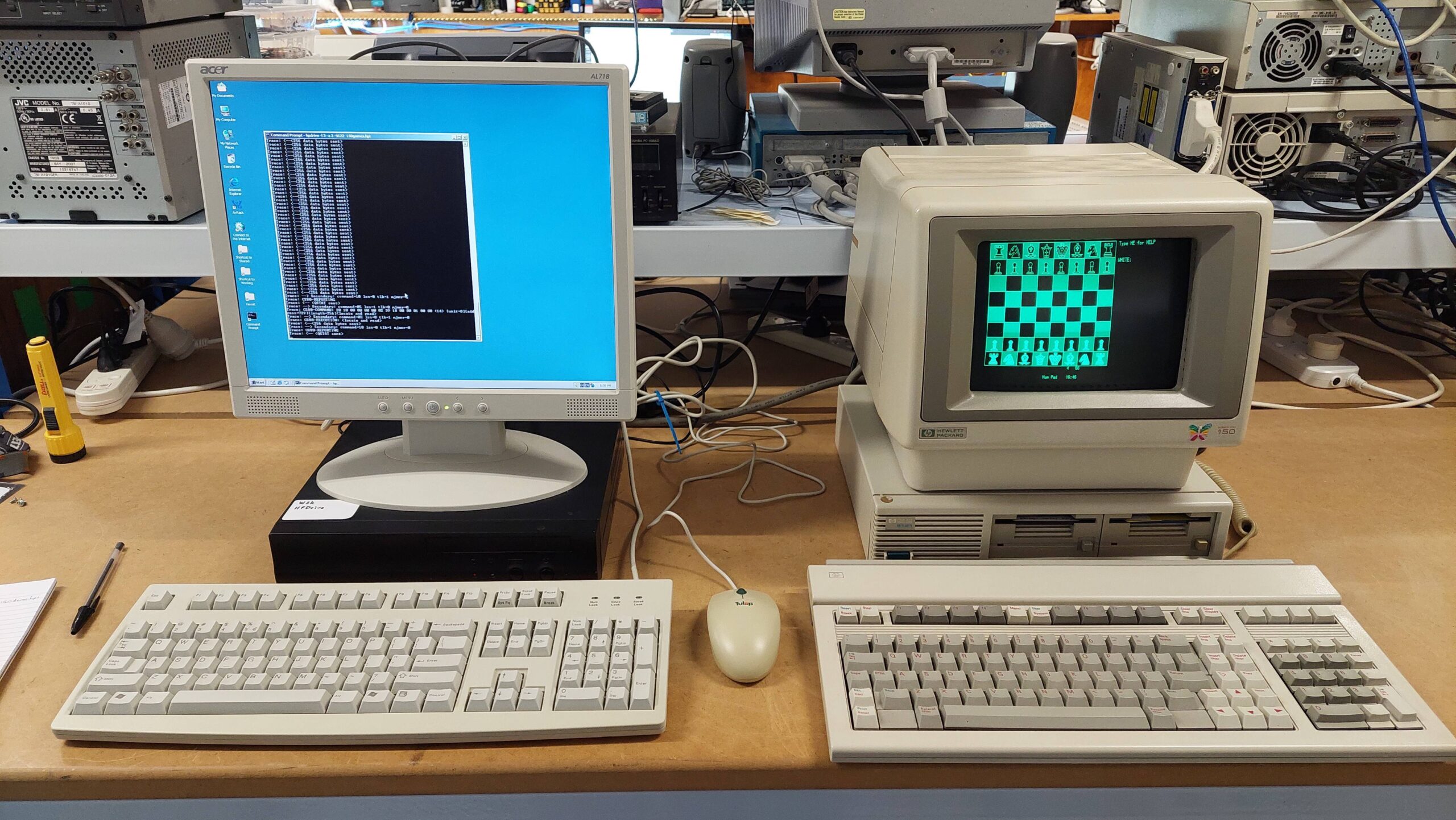
This machine came from Craig M of the ARC group. It is a Data General One from 1984. It is often credited as being the first battery powered IBM compatible(ish) laptop.

The impressively large LCD screen with its unimpressively low contrast is its Achilles heel. If not for that, it probably would have been a very successful machine.
The machine arrived with an expansion box, some disks, and lots of old-school manuals. Much of the software was packaged specifically for the One.
The Data General One Systems Programmer’s Manual contains a lot of technical detail about the machine include specific compatibility issues.
I also found this comprehensive and well-written article very helpful:
https://oldvcr.blogspot.com/2024/03/refurb-weekend-data-generalone-and.html
My story is different in that the machine came with a battery and an expansion unit, but did not come with a power supply. Somewhere along the way i also acquired the external 5.25″ drive unit but not the attachment cable.
Looking at the images in the article and comparing with my unit, i think the screen on mine seems to be somewhat clearer. It does seem to have what looks like some dust behind the panel, and it certainly needs good light (a camping headlamp works quite well) but it is quite useable if that’s all you have. It’s so much better, and clearly has a shade of green, that i wonder if the LCD is the same.
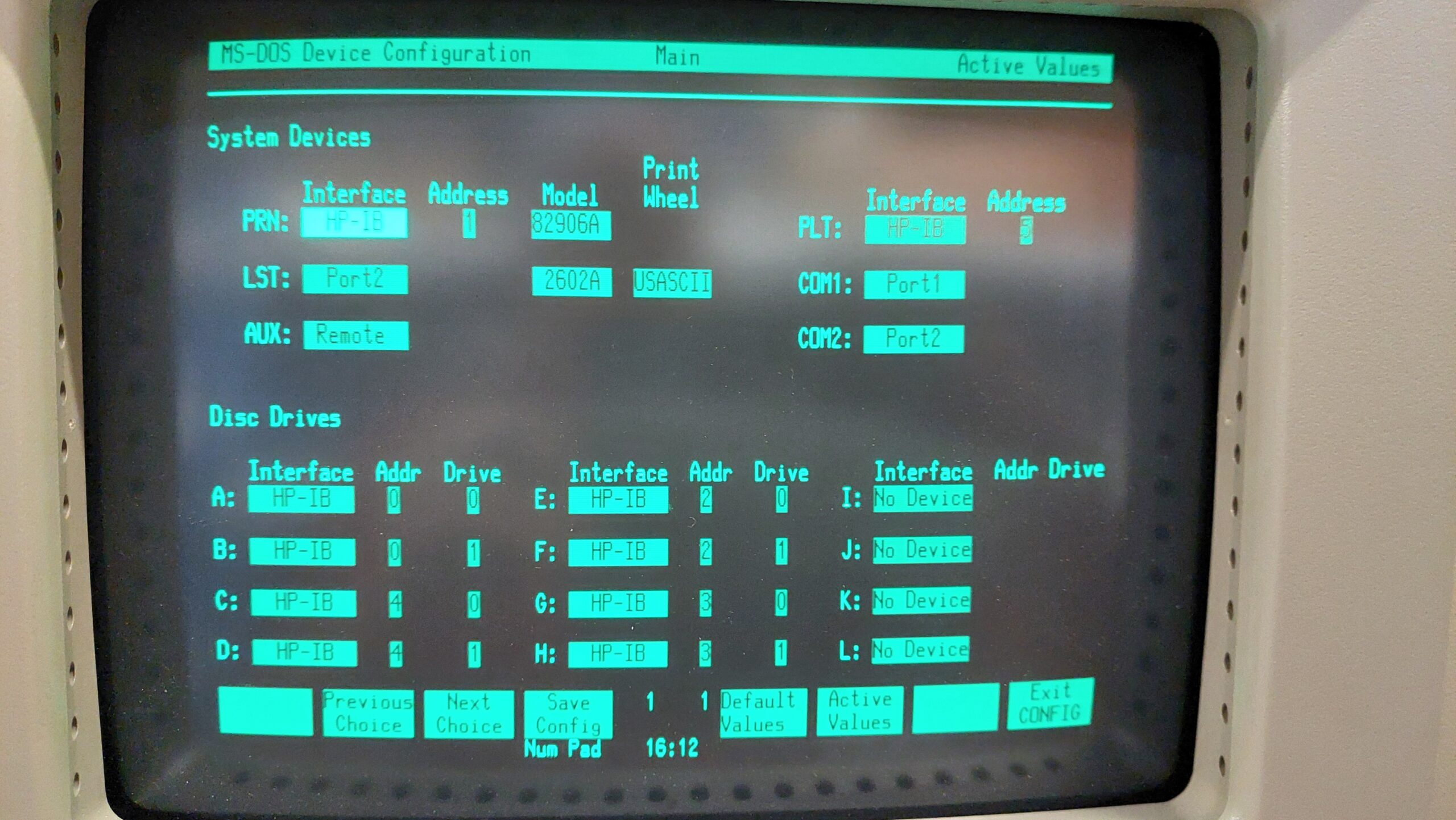
The expansion unit includes a floppy disk controller and 5.25″ floppy disk, a hard disk controller and a IMI hard disk built like a brick dunny, and a printer card. The manual indicated that it was possible for the system to use a CGA card in the expansion unit together with a CGA monitor to provide an external display – a blessed relief from the built-in LCD although far from portable.
The battery is charged from an external power pack, but it came as a surprise to learn that this was not intended to power the computer as well – although, as it transpired, it did do that job with some help from the battery. I couldn’t see this being sustainable.
Without an external supply or even the mating connector, i was forced to jump start it using a bench supply and some croc cables. Later i made up a power supply using an old laptop power supply and an adjustable DC/DC converter. The connector is a bit rough at present.
With power, the computer gave a beep and then, after a delay, it gave a further two beeps. The screen was blank initially but could be adjusted with the contrast buttons (command page-up and page-down). A carriage return allowed the system to boot from the front floppy drive.
Both symptoms were related to the backup battery being very flat. The battery was just a 2025 in a battery holder under the internal modem card.
The system reported a full 464kB of RAM – sadly, 48kB of the physical 512kB is lost to graphics memory. I have no idea whether another 128k can be added in the expansion unit.
I can confirm that the LCD screen is quite awful. It’s curious to me that Amstrad used a similar screen in its PPC512 a couple of years later. It was similarly awful, but at least external CGA was available on the Amstrad base machine.
The expansion unit connects to the computer via a cable and “dock”. The dock plugs into the expansion connector on the back of the computer and is held in place by two screws. When i tried to mount the dock, one of the mating nutserts released itself from the computer, and being worried that some debris may have been fallen inside the machine, i decided to open the unit. I had to anyway, to replace the battery.
Through this process, i learned that it is not necessary to remove the floppy disk drive screws or the keyboard screws.
<picture>

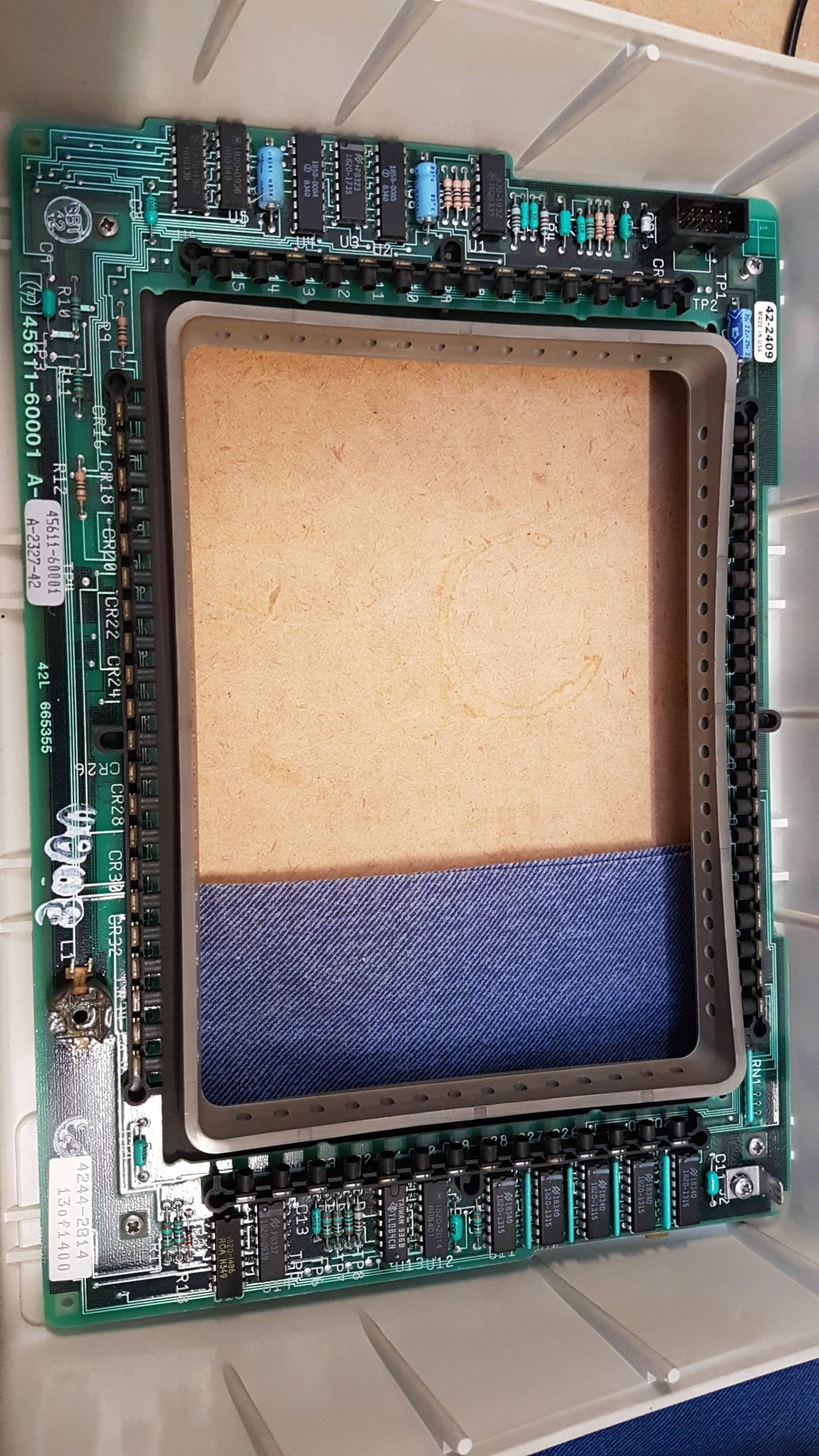
The remainder do need to be removed, together with the 6 metal clips – three on each side. The LCD cable can be released via the battery compartment by pulling up on the top half of the connector. Then the top half of the computer can be lifted and completely removed if the power switch is disconnected.

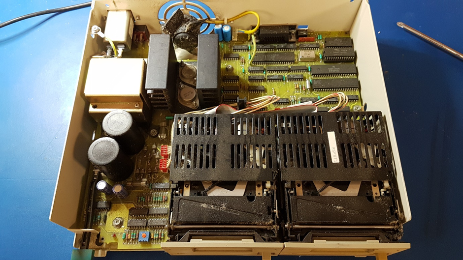
You have to be impressed with the amount of electronics crammed into the unit. There is a lot of surface mount technology for 1984 and the line sizes on the PCBs are very small.
The top card in the stack is the internal modem card. This seems to be controlled through a parallel interface and seems only to be available to the ROM resident terminal program.

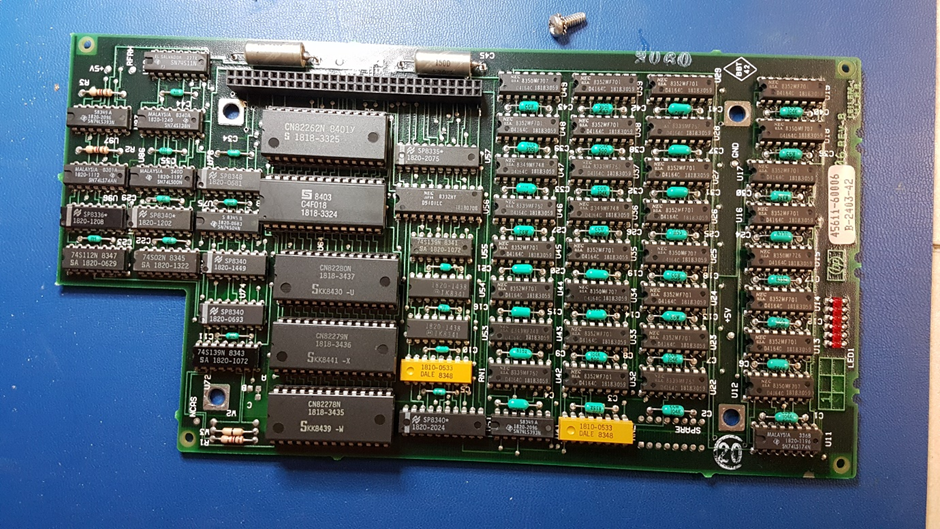
The next card is the I/O card with floppy disk controller, real time clock, and the two serial ports. There’s a ton of surface mount on the back, which i neglected to photograph. The offending 2025 real-time clock battery was replaced.

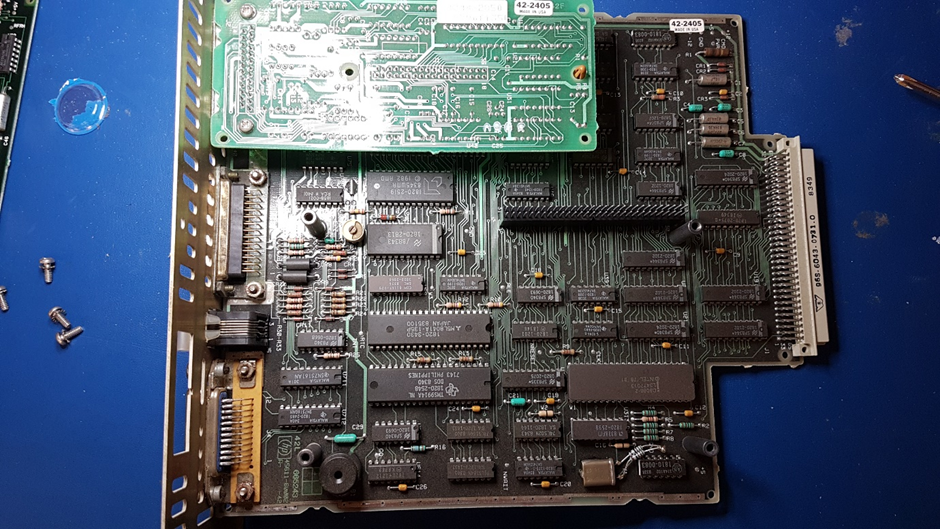
And that’s the main board with the 8088. Most of the cabling has been done with a flexible PCB which is very space efficient. I fear for its longevity, though, as the bends are quite severe.

The memory expansion unit is very cute with three 128MB cards.

After all that, there was no debris, and i cannot see any way to restore the nutsert. I did a full disassembly to clean the keyboard and to have a look at the innards.
Care has to be taken with the main board – the ground springs need to hook under the plastic insulating layer.
I was somewhat aghast to see some scratching on the main board. This is caused by a metal cable retaining clip under the DC/DC converter on the rear panel. I inspected this pretty thoroughly to make sure that no tracks had broken. I added some tape to the metal clip to protect the board. Not great design.
I have not resolved the issue with the dock mechanics, but i pressed on.