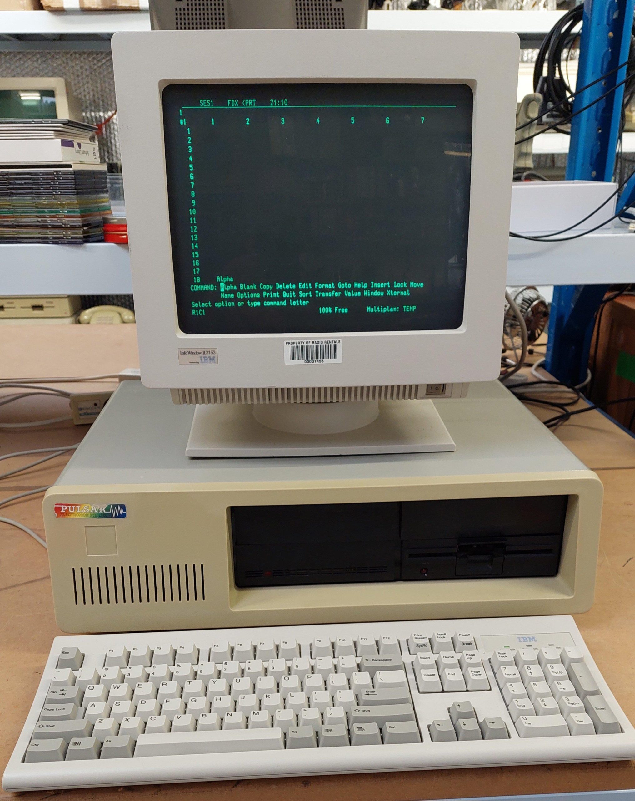
Inside the IBM PC style enclosure are 5 little big boards – one of which acts as a master to control drives and printers. The monitor is an IBM terminal, which is much younger than the computer.
The other four little big boards support 4 users via serial terminals. Each of these is connected back to the master via a serial line. These cards all run Turbodos. Each provides 64kB of memory for running CP/M programs.
The master provides access to a floppy disk drive and a SCSI hard disk – emulated with a SCSI2SD.
I connected it up to a serial terminal, but I couldn’t get anything out of any external serial port. The hard disk did not spin, so it may be a lost cause.
I had no boot disks for the floppy disk, although i thought it may be possible to create some from the 8″ disk collection. Many of the disks were related to Pulsar – both CP/M and TurboDOS.
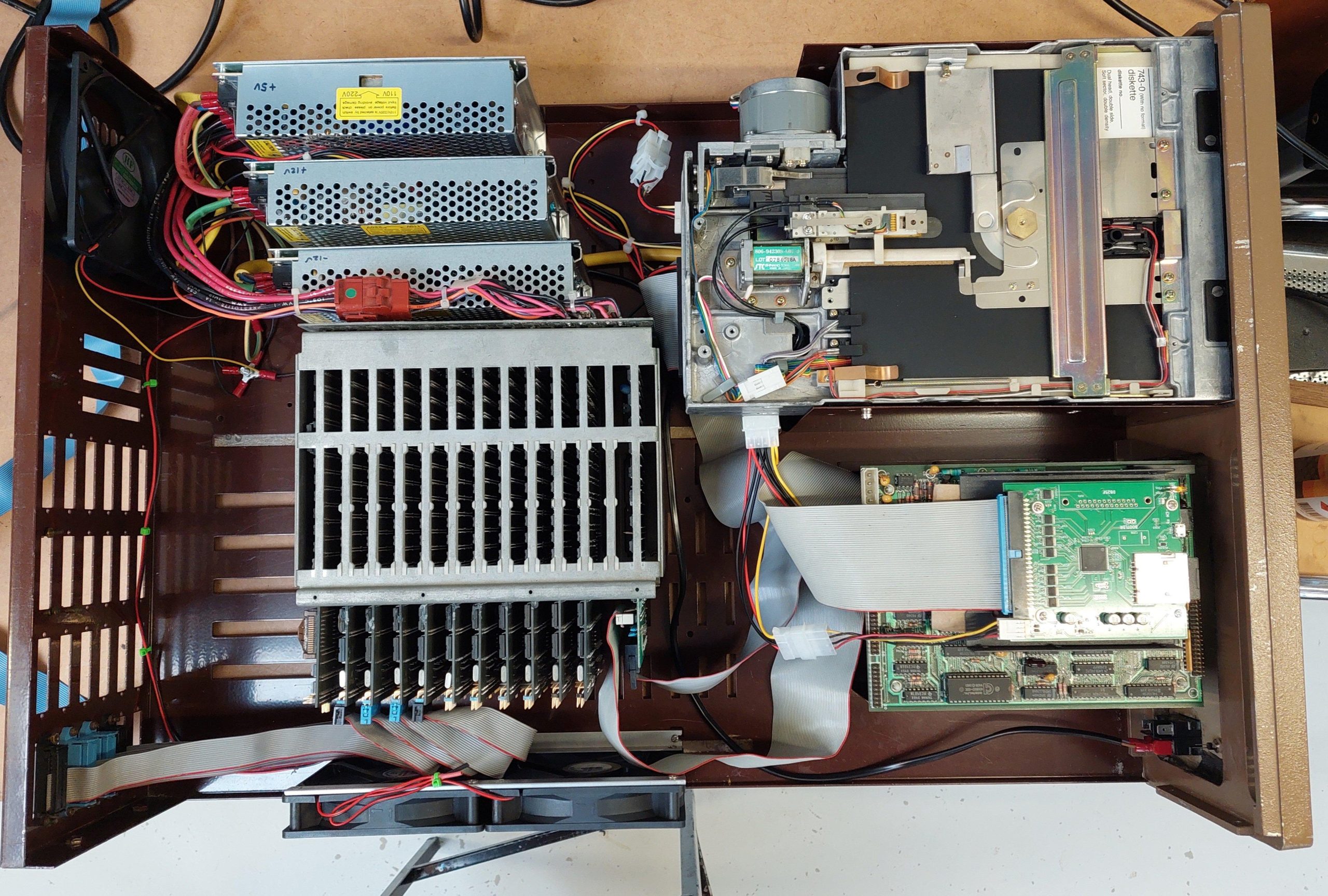
Working in the case was a little cumbersome, so I pulled the system right down to the boards:
It consists of:
1x Master LBB with STD and Floppy Drive Interfaces
4x Slave LBB (with a variety of options which are probably not used)
2x SASI/Dual Serial Boards
1x Mitsubishi M4854-342 High Density Floppy Disk Drive
1x NEC LR 56913Hard disk drive with Adaptec ACB-4000 SASI adapter
1x Sysquest removable disk drive with Adaptec ACB-4000 SCSI adapter (external to computer and mounted on it’s own baseplate)
There is a lot of variation amongst the slaves. Perhaps from card swaps over the years, or perhaps this machine was put together using whatever was in stock. Serial port connectors can be straight or right-angled, a bare header, or a shrouded header, sometimes with release levers.
Each of the slaves is connected via serial to the SASI/Serial cards. The master owns the bus and therefore the SASI/Serial cards. The slaves must not attempt to use the STD bus, so where the interface is loaded it has to be nobbled with track cuts.
There seems to be no reason why the slaves need to be in the unit – they could just as easily be located elsewhere but there is not a lot to be gained as either way a serial connection is required.
The serial ports on the master were used for printers.
I tested each of the boards with an MP7A Monitor ROM in a different chassis.
The master little big board does come up ok, so probably it was silent at switch on because that’s how the boot ROM rolls.
Two of the slaves were ok, but the other two were not working. One had a bad solder joint and the other had lost 12V connectivity because the track is very close to the board edge was severed. The damage would have occurred when I levered the board out of the backplane (there was no other way).
I could not get the master to boot from the floppy disk, even after adjusting the phase-locked loop as per Pulsar instructions. I parked that board and used a spare, which did boot.
From there the configuration tool was used to setup the slaves. There are a lot of questions about each slave. I took the easy options with automatic login of the privileged user.
The 7500 system uses a 5.25” drive rather than an 8″. As it turns out, the floppy disk drive in this unit, Mitsubishi 4854-342, is intended as an 8″ replacement – it even claims to be a 77 track drive although i suspect it’s good for 80.
The 50 pin host interface is connected to the 34 pin drive interface via a simple adapter. All up, this means that the 8” images can be written to HD 5.25” disks.
Looking at the simple 50/34 adapter board, I suspect that the drive has a couple of signals that may not be present on a 5.25” interface – Ready and 2Sides. I imagine that 2Sides is always asserted because there is no way for a 5.25″ drive to know if a disk is single sided. 8″ drives can.
The drive was cleaned and lubricated and tested ok with Imagedisk.
8” Pin
8” SIgnal
5.25” Pin
5.25” Adapter
Comments for Emulation with Gotek
2
TG43_L
Not used
4
6
8
10
2SIDES_L
2
REDWC_L
Not driven by controller or gotek. Pull down
12
14
SIDESEL
32
SIDESEL
16
18
HEADLOAD_L
4
Not Used
20
INDEX_L
8
INDEX_L
22
READY_L
34
DISKCHG_L
24
26
DS0
10
DS0
28
DS1
12
DS1
30
DS2
14
DS2
32
DS3
6
DS3
34
DIRC_L
18
DIRC_L
36
STEP_L
20
STEP_L
38
WDATA_L
22
WDATA_L
40
WGATE_L
24
WGATE_L
42
TRACK0_L
26
TRACK0_L
44
WRTPRT_L
28
WRTPRT_L
46
RDATA_L
30
RDATA_L
48
50
16
MOTORON
I wrote an HD floppy disk from 8″ disk image 8_257_02 (Pulsar Turbo V1.3 Master Configuration Sys 14 Config V24 Single User) using greaseweazle.
Pulsar was an Australian computing company located in Melbourne, Victoria. They made STD cards and computings systems based on the STD bus and often using TurboDOS.
TurboDOS is a multiuser/multiprocessor operating system that can execute CP/M programs.
Eight Z80 processors and two 80186 processors share an 8″ floppy drive and a SASI/SCSI hard disk, supporting 9 concurrent users. Each Z80 user gets their own 64k in which to run CP/M-80 programs, while the lucky 186 user scores 256kB in which to run CP/M-86 programs.
The master board, a 80186 board, loads the operating system from disk and, once it is up, it transfers the operating system to each of the slave cards.
All the rack-mounted cards are bona fide eighties cards. The rack and the 8″ drive are also of the time. The re-construction is new. I was able to find only very scant details of the Pulsar 9000, but i did have a complete set of cards and some software handbooks. It looked like a project!
The Jade Double D is notable for being an intelligent floppy disk controller. The onboard Western Digital FD1791 FDC chip is controlled by a Z80 processor. The CPU communicates with the DD through a 1kB window.
Although the card includes a processor and 2k of RAM it has no ROM. Instead, code must be injected by the CPU card. The code is embedded in the CPU boot ROM.
The boot code assumes that the window address must be set to F400. The jumpers were already correctly set.
This card supports 5.25″ drives on a 34 pin interface or 8″ drives on the 50 pin interface. Eventually i will use 8″ drives with this machine, but in the short term i just wanted to use a couple of goteks (with Flashfloppy).
The images that i wanted to use are from 8″ disks. These work fine in the gotek but because the gotek uses the 34 pin interface there were a couple of residual issues. There are a some signals expected by the boot ROM and the CP/M BIOS for the 8″ drives that are not on the 34 pin interface.
The first is the RDY signal which is supported by Flashfloppy on pin 34. This requires a link on the DD from pin 34 of the 34 pin interface to pin 22 of the 50 pin interface.
The second is that an 8″ drive can detect whether a disk is single or double-sided – the index hole is in a different location. For this, i added a switch to assert or negate the SIDES signal depending on which image i had loaded. I later copied all of the single sided disk images to double-sided disk images to make things a little simpler.
This card had a couple of hardware issues. The first was two shorted tantalums. The second was that, for whatever reason, two sockets had been butchered, and the chips soldered to the socket pins.
The system has two SASI cards that I thought might accept a SCSI2SD card.
The drive configuration comes up in two places – firstly in configuration of the master or single user system configuration program, and then again when the drive is formatted.
In both cases, the following information is required:
SASI card number: 0 worked for one card but I tried multiple numbers with the other card without success
Drive Number: It allows 1 or 2. 1 seemed to be SCSI ID 0.
The configuration also deals with partitioning. The default partition size is 4MB which is the optimal size. With large drives, that’s a bit of a nuisance because you need a lot of partitions. Having some optimal 4MB partitions and a larger sub-optimal partition seemed like a reasonable compromise.
The drive selection gave some geometry, but the specifics probably don’t matter with a SCSI2SD. The SCSI2SD was set up with a simple 32MB disk at ID 0 with 512B sectors. Termination needs to be on.
The process went like this:
Create a fresh single user floppy disk
Run the Configuration program and select modify
Set up the hard disk as above
Format the hard disk using HFORM30 with the same disk parameters
At this point the new drives were available starting at E: but when the directory was listed it appeared the disk was read only and the directory looked corrupted. It didn’t seem to matter if the format was done first and then the configuration.
The “Creating Boot Tracks” section of the System Initialisation Procedure mentioned a program called ERASEDIR but really just in the context of making faster hashed entries. Running this program on each of the drives resolved the issue. It says to run this after BOOTDISC (which writes the boot tracks).
So:
Run BOOTDISK and write to E: – only the first partition can be a boot partition. It can also be written to A:.
Run ERASEDIR on each of the new drives from e: to the last one.
Copy all the files from the A: to E: using DO DCOPY A: E:
When the system is powered up, it looks for a bootable drive. If a boot floppy is in A: it will use it; otherwise it will boot using E:.
Programs were then copied on to the solid state disk from a gotek. TurboDOS supports multiple user areas so the these can be used as directories. User 0 files marked a global can be accessed by all users.
All users are assumed to be using Televideo 950 terminals. A lot of the software on the 8″ disks was configured to use this popular terminal.