ECS 4500 I/O Ports

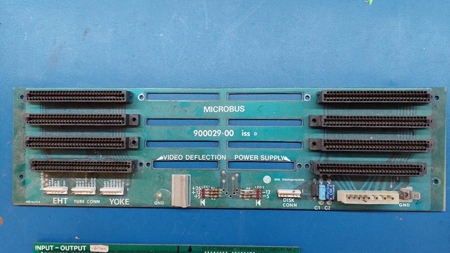
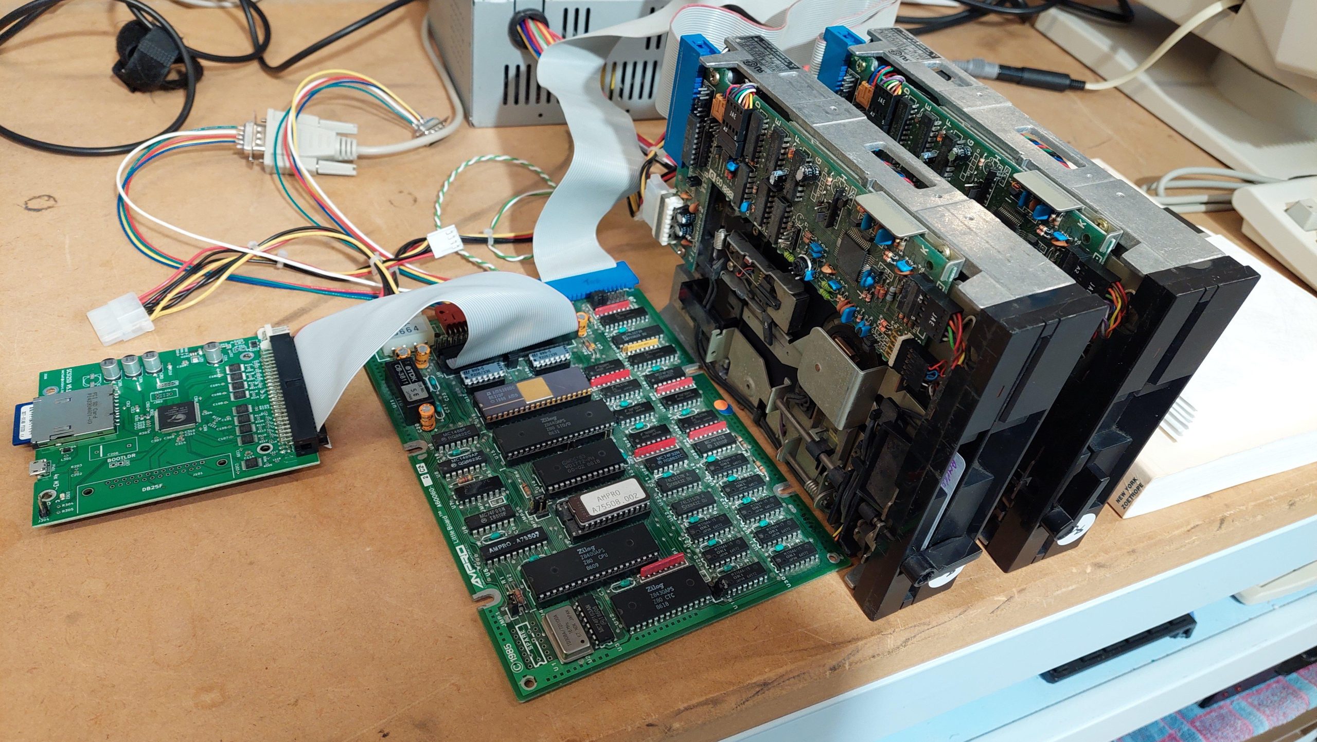
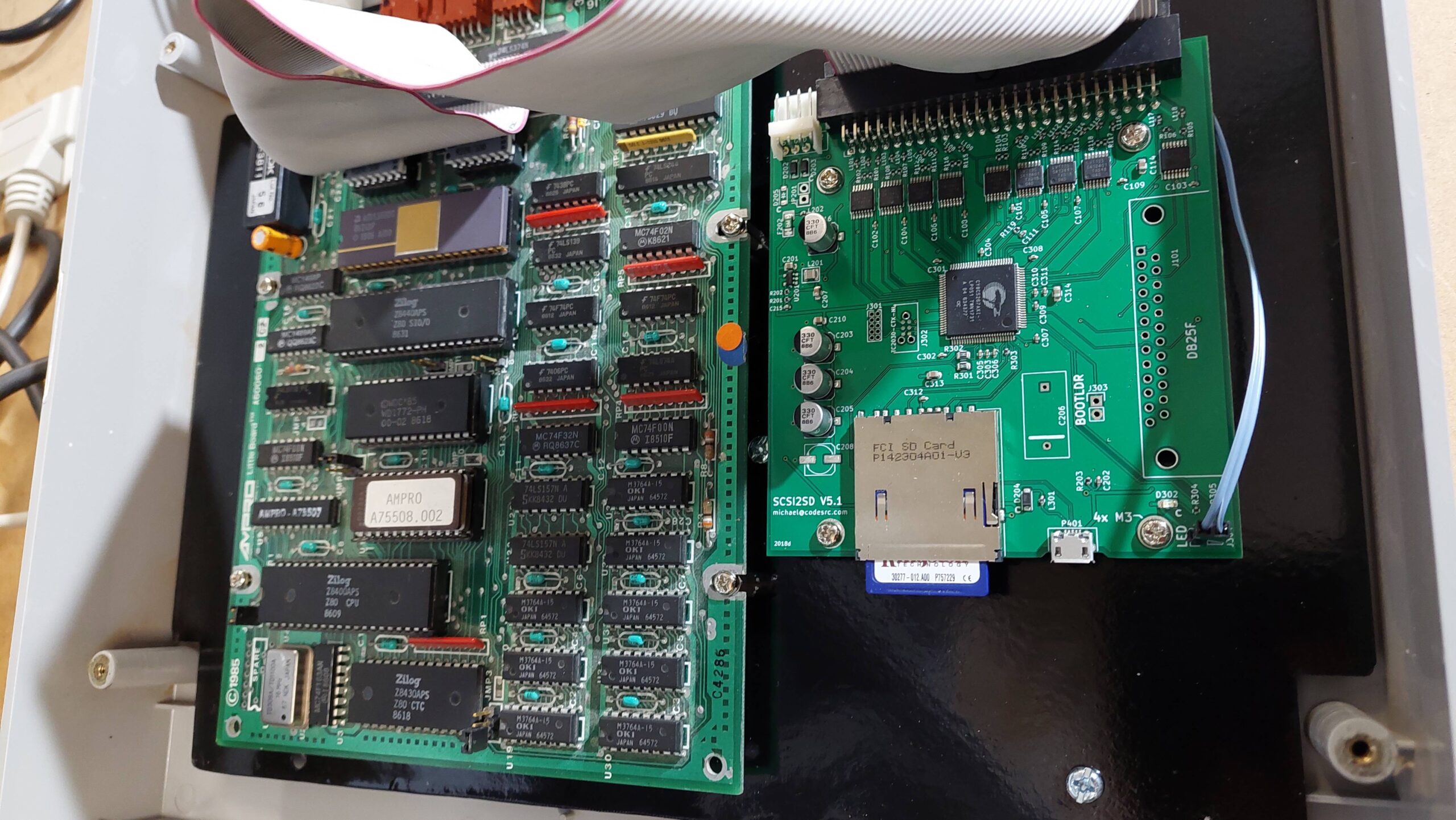
The Input Output board that was originally in the unit did not have PIO so it has been replaced with the spare card.  This may allow the use of a parallel port printer.

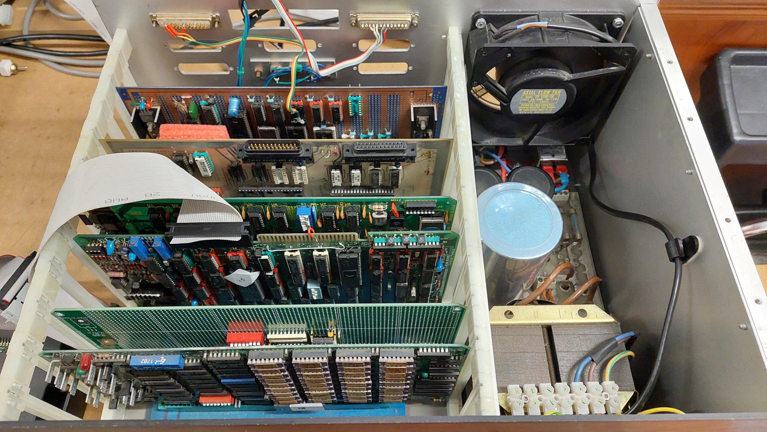
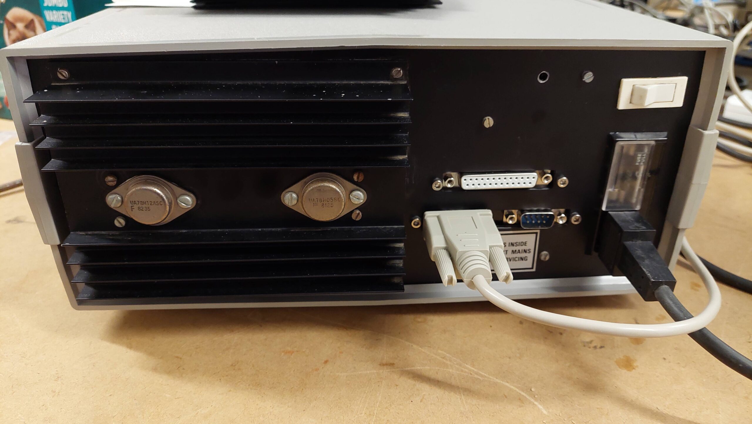
Ports from left to right looking from the rear:

25 Pin Female DDaisy Chain Serial Port on RS232 Buffer board.  Do not use.
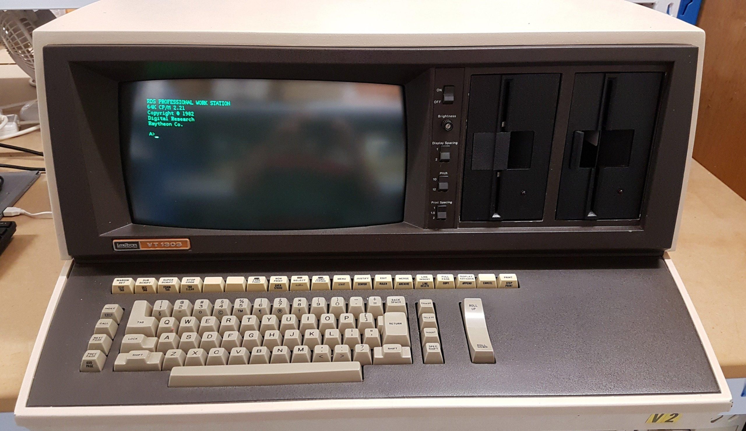
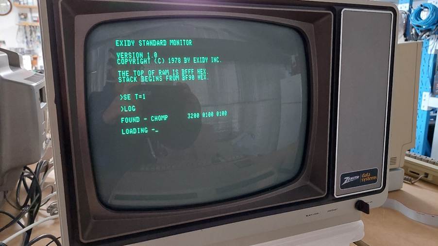
25 Pin Male DSerial Port on RS232 Buffer Board.  This sis connected to the 8251 on the Microcomputer Board.  This port is the terminal connection for dumb terminal built into the monitor ROM and initiated with “t” at the monitor prompt.  9600, 8 bits, no parity.  A null modem was required to connect to a PC. 
25 Pin Female DSerial Port on Datacon board.  This board is connected to the SIO on the Input Output Board.  Level shifting is done on the Input Output Board.  2400, 7 bits, odd parity.  May be configured as the printer port.
25 Pin Female DParallel Port on Intercon Board.  This is different from the original configuration which used a Concat Board. The Intercon Board is connected to PIO Port A on the Input Output Board.  This may work with a parallel printer but without success so far.

System configuration is important to make these devices work.

The DIP switches on the I/O Board may have an effect.  There is some info in the manuals, but it is patchy.

ECS 4500 Bus

I attempted to reverse-engineer the bus, but i stopped short of the processor bus.

Video Deflection

Solder SideComponent Side
GndGnd
5V5V
12V12V
-12V-12V
-5V-5V
+26V+26V
  
WriteWrite
WriteWrite
HorizontalHorizontal
VerticalVertical
VerticalVertical


HeaterHeater
HeaterHeater
CathodeCathode
Grid 1Grid 1
Grid 7Grid 7
Grid 2Grid 2
  
  
+26V xxx+26V xxx
  
+400V+400V
+68V+68V
5V5V
GndGnd

Power Supply (pretty sure there are a few errors here!)

Solder SideComponent Side
GndGnd
+5V+5V
+12V+12V
-12V-12V
-5V-5V
26V26V
  
  
9VAC9VAC
9VAC9VAC
9VAC_Ret9VAC_Ret
9VAC_Ret9VAC_Ret
16VAC16VAC
16VAC_Ret16VAC_Ret
  
  
GndGnd
GndGnd
GndGnd
  
26VAC26VAC
26VAC_Ret26VAC_Ret
  
  
13VAC13VAC
13VAC_Ret13VAC_Ret
  
+5V+5V
+5V+5V
GndGnd

Microbus

Solder SideComponent Side
GndGnd
+5V+5V
+12V+12V
-12V-12V
-5V-5V
26V26V


+26V+26V
-5V-5V
-12V-12V
+12V+12V
+5V+5V
GndGnd

Lexitron VT1303

It was never my intention to buy this machine.  I drove out to Lewiston (just north of Adelaide) to collect another purchase, and the seller asked if i would be interested in this mammoth. It had apparently come from a South Australian government department, but had been subsequently used by the seller and his family for several years during the eighties.

I did some quick research and found that it was a word processor – not really my cup of tea.  In the end, i bought it for about the value of the two drives.  It also came with a daisy wheel printer, a long and heavy-duty printer cable, a couple of manuals and some beaten up looking disks.  The screen looked like it had some kind of disease, which was later identified as CRT cataracts.

I was happy to find that the drives were Shugart SA400 drives because these are the first really successful 5.25″ drives.

Backing up the disks was an exercise in itself, but once done, i set the machine to work.  I replaced a shorted tantalum and gave the drives some love. I started the machine up and, surprisingly, the machine booted into its word processing program.

Mild joy was short-lived: the keyboard did not work, and it was the microcontroller that had failed.  At this point i should have pulled the drives and some other spares and sent it off to the recyclers.  Instead, i built a teensy based replacement for the microcontroller and reverse engineered the keyboard.  This act of madness yielded a system that was close enough to demonstrate the machine as a word processor.

Along the way, i had picked up hints of CP/M being available for this machine.  I periodically did google searches to see if there might be some images kicking around and to my surprise about 3 years later they appeared on archive.org (thanks to the person who did that – dasher perhaps).

Once written, with some help from an Adelaide Retro Computing Group member (thanks Mick S), the machine was able to boot to CP/M and take on a new life as a computer.

If the success of a vintage computing purchase is measured by the hours endured to get it working (the primary entertainment value), then this machine has certainly delivered.

For a little history of Lexitron see the video here:

Pulsar 7500 Computer

This computer is not what it seems.

Inside the IBM PC style enclosure are 5 little big boards – one of which acts as a master to control drives and printers. The monitor is an IBM terminal, which is much younger than the computer.

The other four little big boards support 4 users via serial terminals. Each of these is connected back to the master via a serial line. These cards all run Turbodos. Each provides 64kB of memory for running CP/M programs.

The master provides access to a floppy disk drive and a SCSI hard disk – emulated with a SCSI2SD.

The construction is a bit rough and ready!

Pulsar 9000 Computer

Pulsar was an Australian computing company located in Melbourne, Victoria. They made STD cards and computings systems based on the STD bus and often using TurboDOS.

TurboDOS is a multiuser/multiprocessor operating system that can execute CP/M programs.

Eight Z80 processors and two 80186 processors share an 8″ floppy drive and a SASI/SCSI hard disk, supporting 9 concurrent users. Each Z80 user gets their own 64k in which to run CP/M-80 programs, while the lucky 186 user scores 256kB in which to run CP/M-86 programs.

The master board, a 80186 board, loads the operating system from disk and, once it is up, it transfers the operating system to each of the slave cards.

All the rack-mounted cards are bona fide eighties cards. The rack and the 8″ drive are also of the time. The re-construction is new. I was able to find only very scant details of the Pulsar 9000, but i did have a complete set of cards and some software handbooks. It looked like a project!

8085/86 Compupro/Jade System

An enthusiast build – and i couldn’t even be sure that it’s complete.

Andrew, a friend from the ARC Group, has supplied me with a lot of funky gear including a box of S-100 cards, a couple of chassis, several 8″ floppy disk drives, and about 500 8″ floppy disks.

One of the challenges is that the relationships between all this kit was not obvious. This one i was only able to sort out because i found the source for some boot ROMs on one of the floppy disks. Even now i’m not sure if i have the original RAM card but the one i’m using does just fine.

It uses the following cards:

  • Compupro 8085/86 CPU Card
  • Jade DD Floppy Disk Controller
  • A handcrafted wire-wrapped Serial & Parallel I/O and Speech Synthesiser card
  • A parallel card with real-time clock
  • Intersystems 256KDR
  • A recently constructed EPROM Card

I have not connected an 8″ drive to it as yet, but it boots JADE CP/M 2.2 from a gotek. The disk images are from the original floppy disks.

Ampro Little Board Plus

This is one of my current projects. It is based on the Ampro Little Board Plus which is a single board computer designed to be mounted on the back of a 5.25″ floppy disk drive.

It uses a Z80 processor running at 4MHz and includes two serial ports, one parallel port, a floppy disk controller and a SCSI controller. It runs CP/M 2.2 and is happy to boot off a floppy or hard disk. I’ve added a SCSI2SD to emulate several 20MB hard disk drives.

The user interacts with the machine using a serial terminal.

I started off with the two 40 track Mitsubishi drives shown but have been using a gotek (with FlashFloppy) for the software load.

Currently, i’m loading up a whole bunch of software from images created using cpmtools. Eventually this will be mounted in an external drive enclosure.

AMPRO Little Board – SCSI2SD

I used a scsi2sd card with a 256MB sd card.

This took me a bit longer than I expected because I didn’t read the instructions.  CP/M needs to be configured to have some hard disk buffer space, otherwise the format fails mysteriously.  I changed it from 60k to 56k.  That allows room for the maximum 88MB of total disk storage.

The hformat program allowed for different controllers but after some experimenting I found success with the Seagate ST-225N hard disk. 

+-----

Form                 5.25"/HH              Cylinders     615|     |     |

Capacity form/unform    21/   25 MB        Heads           4|     |     |

Seek time   / track  65.0/20.0 ms          Sector/track   17|     |     |

Controller           SCSI1 SINGLE-ENDED    Precompensation

Cache/Buffer               KB              Landing Zone      670

Data transfer rate          MB/S int       Bytes/Sector      512

                      1.500 MB/S ext ASYNC

I set up sd2scsi with 7 drives each with 615 x 4 x 17 = 41820 sectors of 512 bytes.

I used hinit (with burst mode) to set up 2 partitions on drive 0 and drive 1:

  • 8192k
  • 8192k

This needs to be done on every boot (really? yes) but an alias can be created:

alias

HINIT YD010 AF8192 AG8192, YD110 AF8192 AG8192,.

hardinit

then another alias that does this and swaps the drives over:

alias

HARDINIT; SWAP AF BG CH DI; STARTUP

HSTART

Startup can contain whatever is wanted, eg a menu program.

HSTART can be run on boot by adding at item 5 in the config program.

Copy the system track from the boot floppy to the hard disk using SYSGEN (watch out for the letter swapping).

Less than obvious (it’s in a separate section of the hard disk software manual right at the end) are instructions for autostart, noting HGEN in particular.:

When the system starts, it looks for a boot floppy. If it finds it, then it will boot from it.  If it doesn’t find it, in about 10 seconds it will boot from the first hard disk partition.  For some reason it keeps looking for a disk in the first floppy disk drive.  If you give it one it stops but does nothing with the disk.

AMPRO Little Board – Enclosure

The Little Board was designed so that it could be mounted to a 5.25″ floppy disk drive. In keeping with this vibe, it uses a floppy disk drive power connector with just 12V and 5V; -12V for RS232 is generated on the board itself.

With this in mind, i thought that perhaps a disk drive enclosure could be a useful starting point. I had bought a hard disk in an external enclosure at a swap meet, but i was unable to find any information on the interface. I figured that the drive within would not be reliable in any case.

The enclosure has a heavy linear supply providing +5V and +12V. The drive itself is a full height 5.25″ drive, so there is sufficient accommodation for two half height floppy disk drives.

I figured that i could sequester unused parts, including the hard disk, just in case i wanted to return it to its original state.

I wanted to include a physical floppy disk drive, a gotek emulator, the Little Board, and a SCSI2SD card. If i mounted the Little Card to the floppy drive then it would have been underneath which would make it difficult to access the connectors.

Instead, i created a “baseplate” to accommodate the Little Board and the SCSI2SD. I mounted the baseplate on the top cover.

I replaced the perspex front panel with a new aluminium panel with a cutout for the drives and holes for power and hard disk lights and a reset switch.

Both the front panel and the baseplate were earthed. I used metal standoffs and cleared paint so that they would ground the cards.

The front panel got a couple of coats of gloss Bermuda blue.

The enclosure had a couple of cutouts for connectors, which gave enough space for two 9 pin serial ports and the 25 pin printer port. I made up a custom panel to overlay the existing cutouts.