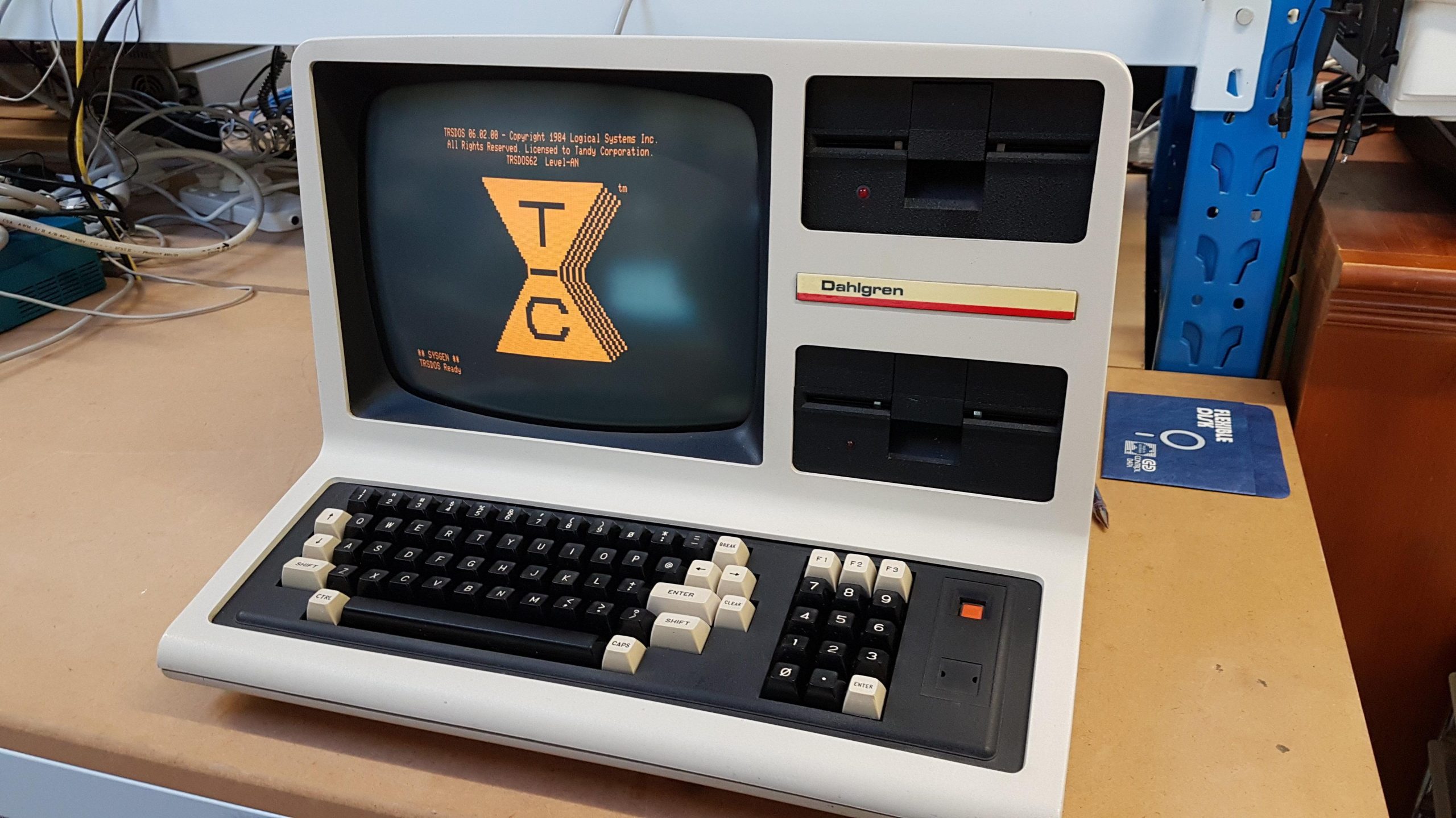
The System 80 came with a Thorn 7433 black & white TV that was used as a monitor. It had had a couple of homebrew additions.
The first was a composite video input, so modulation/demodulation is redundant.
The second was a green screen, which was appropriately agricultural. The mount has broken and in any case is too rough even for my low standards.
It seems to be working fine.
I have removed the mount, and rubbed back the glued areas. It’s currently awaiting paint and then i’ll attempt to mount some coloured perspex that looks a little more appealing.
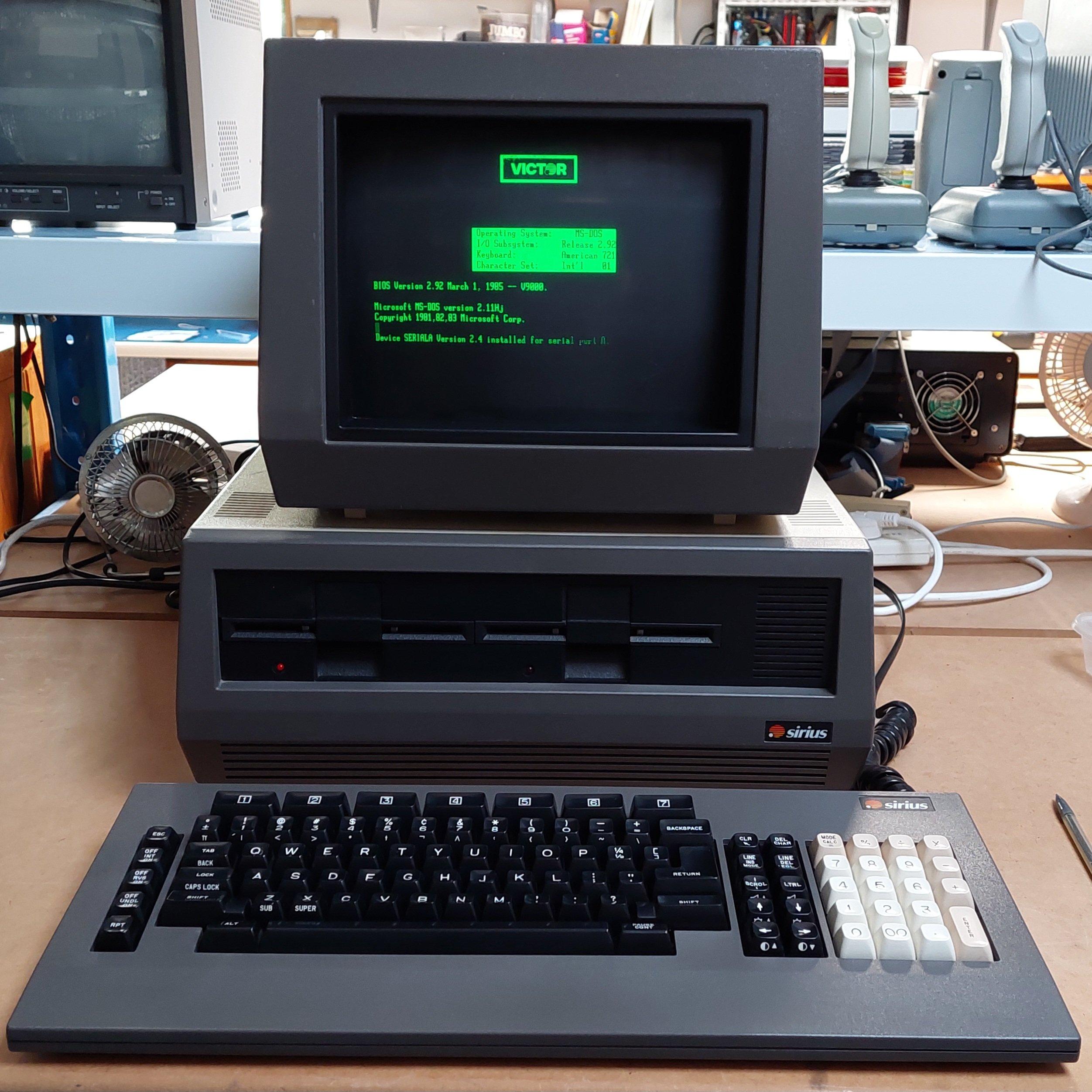
The Sirius One was a moderately successful attempt to produce a 16 bit business machine using MS-DOS and CP/M-86. It was targeting a similar market of that of the IBM PC and although it runs the same operating systems as an IBM PC it is not a PC-compatible. Both machines were released in 1981.
The machine was sold as the Sirius One in some markets and as the Victor 9000 in others.
It was designed by Chuck Peddle, who is famous for designing the Commodore PET. It sold well in the UK and Europe.
The Sirius One did have some significant advantages over the IBM PC, including 800 x 400 pixel graphics, more sophisticated sound, and 600k single-sided 80 track 5.25″ drives.
The drives used variable speed to more efficiently use the longer outside tracks. The Apple Macintosh 3.5″ drives used a similar approach.
Furthermore, it has some nice touches like prompting for disks with icons and automatically detecting disks. It is happy to boot from either drive.
Soft keys for contrast and audio volume also add to the feeling that this computer is quite highly evolved for 1981.
Like the IBM PC, it had expansion slots – but not the same as the IBM ISA slots.
This particular machine was spotted by a ARC colleague, Mike, at a former recycling depot. It had been a little mistreated during the “about to be recycled” process, but nothing too severe.
It has 128k of memory on the main board and another 128k on an expansion card. Printer and serial ports were built in.
I think the monitor should be sitting on a pivot base, but that must have been lost along the way.
The Monitor required a simple cable repair after some rough treatment. It’s powered from the main unit.
I inspected the power supply. Somebuddy had powered the unit on fairly recently, probably in preparation for sale, and one of the line filter capacitors had smoked. I replaced 3 X and 2 Y capacitors. I load tested the power supply, and it was good to go.
The drives were in very good condition and i just cleaned and lubricated the rails. One drive light is a little dull.
Overall, the machine gives an appearance of far greater quality than an IBM PC. It comes apart easily.
Looking from the top: Floppy Disk Controller. Three spare slots on the expansion bus.After Floppy Disk Controller has been removed: Motherboard128k Memory Board
The keyboard is not great. The foam pads will need to be replaced (like a Compaq Portable or Kaypro II).
The machine did not come with any floppy disks. Fortunately, there are a lot of disk images available online.
Writing them is a bit of a challenge because of the unique format. They need to be written with an 80 track drive but with double density. I used a Panasonic JU-475-5. I tried another drive (Newtronics), but it seemed to only write reduced current for high density disk media.
Fluxengine supports the disk format and is happy to write it using a greaseweazle:
I found this method a little prone to crashes. The alternative is to convert the images to scp format using fluxengine, and then write the scps using greaseweazle. This does not verify the writes, though.
I now have the fluxengine hardware so that’s a third option to try.
The screen is very sharp. The brightness is controlled with soft keys. The monitor has an antiglare mesh built in.
High density 5.25″ disks have much the same capacity as 8″ double density disks, and they operate at the same data rate. A 5.25″ FDD typically has a few more tracks than an 8″ FDD.
This means that a floppy disk controller expecting to see an 8″ disk drive can potentially be fooled into working with an HD 5.25″ drive. This can be very handy if you don’t have an 8″ drive or if you want a more compact setup. This trick seems to work ok with a real HD drive or with a gotek/flashfloppy. 8″ disk images can be written to HD 5.25″ media without alteration using Greaseweazle, for example.
There are a few small issues. The first is the 8″ drive interface is usually 50 pins and the 5.25″ interface is usually 34 pins. The disk controller may have both interfaces (eg the Jade DD and the 16FDC) but not always (eg the Pulsar Little Big Board only has a 50 pin interface). If there is no 34 pin interface, then an adapter will be required. The 50 pin interfaces vary a bit, so a specific adapter may be required.
The second is that 8″ drives can detect whether a drive is single or double-sided and tell the host. The operating system driver may exploit this information (eg Jade DD CP/M) so there may need to be a way to fake this. For systems that use only single sided or only double-sided disks the signal can be tied appropriately otherwise a switch may be required – and if there are different drives in the system then it may be necessary to take the signal low through a diode from the drive select line.
Third is that 8″ drives typically produced a ready (RDY) signal. Without this signal, a host may just hang. This signal is available on many drives and can usually be setup on a gotek/flashfloppy but it may not be connected on the 34 pin interface. This can be overcome by connecting pin 34 on the 34 pin interface to the appropriate pin on the 50 pin interface.
This is one of several machines that came from a ARC Group member, Andrew, who was rehoming his brother’s collection. Andrew has been remarkably generous, and that generosity has made a lot of things possible that otherwise would not have been.
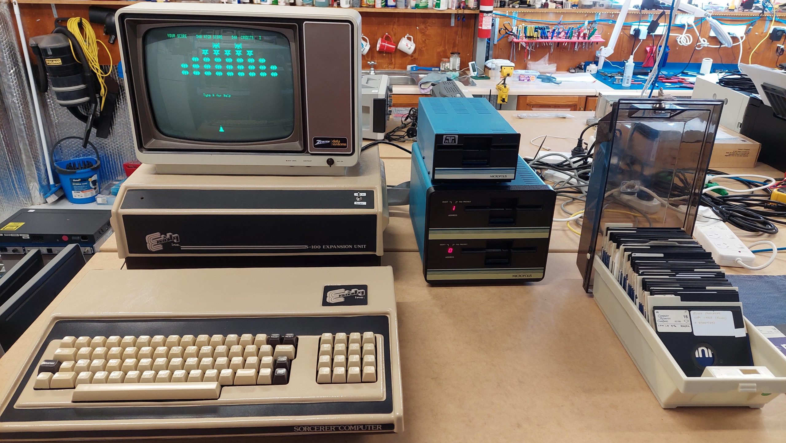
The Exidy Sorcerer represents the transition from S-100 microcomputers to more integrated designs. The computer unit with integrated keyboard has 48k of memory, rompac cartridge slot, video out, serial and parallel I/O ports, and an expansion bus. When used alone, the machine typically had a a basic ROM cartridge and programs were loaded from and saved to cassette. The machine has quite high graphics resolution compared to the other computers. Graphics were drawn using programmable characters.
Michael Borthwicks’s excellent presentation on the Australian applications of the Sorcerer from VCF Canberra is here:
This machine appears to have been used by a business. The expansion unit connects to the computer via the expansion port. It provides 4 S-100 slots. This was used mainly for a disk controller – in this case a hard sectored micropolis unit that operates with up to four unusual 77 track 100 TPI disk drives. It boots Micropolis DOS, Exidy CP/M, Lifeboat CP/M and Software Source CP/M (i don’t have a complete system disk for this Aussie rolled version).
The disks are challenging to read and write, but fluxengine did the job for me, and greaseweazle is now also capable of working with these disks. Hard sectored disks are unusual. Fortunately i have enough but i have a virtual sector generator as well so that soft sectored disks can also be used.
I have also added an 8kB memory card to the expansion unit at the same memory location as the rompac slot. Basic can be loaded into the card so that programs for the rompac basic can be executed.
The disk drive looked awful inside and out and once the loose debris was removed it still looked awful.
The cover was very corroded and the IEEE-488 connector was broken although the pins were intact.
After a wipe over, a blowout, and a first board wash started to look a little better with the board appearing to be less corroded than the computer boards.
There was no rush to get the drive going because I didn’t have a computer to test it with, and I didn’t have a connecting cable. I ordered a short GPIB cable from China and an edge connector locally with a view to modifying the standard cable.
PCB corrosion was treated with soapy vinegar and after two passes the board was quite acceptable. The IC legs were in much better condition than those on the computer boards.
The tin can was treated with deoxit over several days and was then cleaned and painted with zinc paint.
The drive was thoroughly cleaned and lubricated. It had no corrosion and the head carriage moved freely.
The case was processed in much the same way as the computer bases. See above. The corrosion was severe enough that filler was required. I’m at a loss to explain why the case was so corroded but the PCB was good – despite the ventilation slots on the top of the case.
Transformer voltages were checked before power on. I was surprised to find that the drive started with a spin and then gave a solid light as per the manual. This was a good sign.
Alas, smoke followed, which is when I realised that there was probably a Rifa hidden away inside the IEC inlet filter.
Although I had a spare filter, it was too large to fit under the wiring cover, so I have reverted to a simple inlet with no filter. I don’t like doing this, and I will revisit in the future.
I made up the cable by unpicking one of the GPIB connectors and replacing it with an edge connector. The supplier sent the wrong size, so I had to cut it down to suit (2×12 rather than 2×22).
I made up a 2031 demonstration disk using a greaseweazle and a 40 track drive. I had trouble doing this via SCP, but it worked fine writing direct. Initially the drive was unreliable, but after a more exacting cleaning of the head it ran and passed the drive performance test.
Most games were written for 40 columns, so for the 80 column machine to work it has to run in a 40 column compatible mode. This is done by running a program which effects the changes: CBM4032.
The program was easy enough to find, but I had to put it in a disk image. As is often the case, there’s an app for that. I used DirMaster. Then the image just has to be written with greaseweazle.
I found that sometimes the disk drive stopped working. When it did, it is because the head carriage was not moving reliably. My best guess was that there is an intermittent fault in the stepper motor drive circuit. It did not seem to be the connector.
The soldering on the board looks very good.
When the drive worked it worked very well, so the fundamentals seem good.
I used the scope to have a look at the stepper motor drive signals. One was not like the others. The stepper is driven by a quad resistor array FPQ3724. The transistor at pins 12,13,14 did not seem to be presenting a 0.7V drop in operation. On the meter it looked fine. Pin 14 was quite corroded, so perhaps some moisture had got in. It’s also possible that it had just blown – not unusual. An identical array is quite hard to get so in the short term I’ve patched a BC337 transistor in parallel. This seems to have resolved the problem for now.
This is a long technical post. There’s probably only one reason to read it: you have a Lexitron with a broken keyboard. I’m not going to polish it much, but I leave it here just for you!
I spent a lot of time creating a teensy replacement for the microcontroller in the keyboard. One of the great challenges was to work out the key codes sent from the keyboard to the 8085. This was very time-consuming and there were some that I never really cracked.
With the arrival of working keyboards, I could just swap out the original for one of the working units. Buuut the teensy solution actually provides a mechanism to move data from a modern PC to the Lexitron and that’s handy. Also, I guess I’d like to just close the loop!
I can now sniff the communication between the 8085 and the keyboard microcontroller. Because the keyboard appears to be just another device on the 8085 bus the data is transmitted as a parallel byte. This would be easy to sniff with a logic analyser, but not so easy with an oscilloscope. I thought my Analogue Discovery 2 might be sufficient for this task.
Two Different Keyboard Types
One of the VT202 units uses the same Cortron Keyboard as the VT1303. The other uses a Digitran keyboard which looks quite different but seems to be entirely compatible with the Cortron. The Digitran sound is not as loud.
Revisit Operation
Keyboard Pinout
Pin
Name
Function
1
+5V
2
+5V
3
GND
4
GND
5
NC
6
GND
7
Strobe_L
This line indicates activity on the keyboard. It is asserted for 5us when a key is pressed and for 10us when a key is released. The strobe is not asserted when a front panel switch is changed. It is not asserted when the shift key is pressed. It is asserted for spec shift.
8
D5
9
D6
10
GND
11
D7
12
D4
13
Kbd_Read_L
This line causes the keyboard to put data on to the 8085 bus. The read occurs about 100us after the strobe is asserted. A0 is low. Scan code? A second read occurs about 8us after the first. A0 is high. Switch state? This strobe is asserted a couple of times every 10ms (approx.)
14
Screen On
This also appears in the status register.
15
A0
This selects the data that is read by the 8085 – either the keycode or the status of the front panel switches.
16
Kbd_Write_L
This strobe is asserted about 5us after Read is asserted in response to the Strobe. This strobe is asserted every 10ms (approx.)
17
Reset?
18
GND
19
D3
20
D2
21
D1
22
D0
23
-15V
24
-15V
25
+15V
26
+15V
Character Register
Bits 6:0 = Character number

Bit 7 = Shift
Status Register:
Bits 1:0 = Print Spacing

Bit 2 = Pitch

Bit 3 = Screen Spacing

Bit 4 = Not used (input pulled up)

Bit 5 = Key pressed

Bit 6 = Screen On/Off

Bit 7 = Autorepeat (although it doesn’t seem to be used)
Command Register:
Bit 0 = Key click

Bit 1 = Type Through LED

Bit 2 = Select LED

Bit 3 = Continuous Typing LED

Bit 4 = Write LED state (Bits 1, 2 & 3)

Bit 5 = Acknowledge

Bit 6 = Bell (Not supressed by volume control)? Under CP/M this is sent when Select is pressed.  Select causes an alarm chime (not volume controlled).

Bit 7 = Unknown
Adjustable volume applies to key strokes. Alarms have a fixed volume.
Word Processing Program Behaviour
Periodic
Once every 10ms or so the program reads the status register and writes the Command Register.
Keystroke
When a key is hit the keyboard alerts the uP by asserting Strobe_L for 5us. The program responds by reading the character, reading the status register, and then writing 32 to the Command Register. This seems to be an acknowledgement. If there is a LED change or sound then that will be sent a few milliseconds later.
The key release is also acknowledged with a command write which can update the LED state and sound a bell but I think does neither.
The unit only autorepeats on space, backspace, dash, underline, and full stop. This auto repeat is convoluted. It involves resending a specific character after the wait time has elapsed. This triggers the software to autorepeat. It looks like the bit 6 of the status word is set at the same time. This is set by an output from the microcontroller (Pin 29). Although the original keyboard does this it does no appear necessary.
Character
Original Output
Autorepeat Output
Space
80
112
Dash
103
119
Underline
231
247
Full stop
26
122
Backspace
110
126
I can’t see any obvious pattern in these numbers. They just are.
CP/M Behaviour
Periodic
Once every 10ms or so the program reads the status register.
Keystroke
When a key is hit the keyboard alerts the uP by asserting Strobe_L for 5us. The program responds by reading the status register, reading the character, and then writing the Command Register – it can acknowledge, set LEDs, or make a sound.
The key release is also acknowledged but the LED data is not repeated. There is no periodic write The key release is also acknowledged with a command write which can update the LED state and sound a bell but I think does neither.
CP/M autorepeats on most keys but not Spec Shift or Sel. It initiates a beep on each auto repeated character.
CP/M politely ignores the autorepeat shenanigans that the keyboard does for the word processing program.
In CP/M lots of keys are defined as function keys that can be changed using the config program. The config can also control auto repeat and key click.
Select is a caps lock key.
My Current Keyboard Code
The current routine that I have for sending a character to the 8085 sets up the character and then takes then asserts the strobe (indirectly) for 1ms. It then sets up another character (usually zero).
The real thing asserts the strobe for 5 or 10us. Both the key register and the status register are read within about 100us of the strobe. The Command Register is then written. This may be the trigger to clear the key but maybe not. I previously concluded that the key needed to be nulled but I’m not sure why it does.
My implementation autorepeats on all keys except “mode” keys like Spec Shift and Margin Set. The actual unit does not autorepeat, although the software does under some circumstances.
I’ve treated Spec Shift and Margin Set as special cases because they are used in combination with other keys. Certainly, autorepeat doesn’t apply. CP/M treats Margin Set as a normal function key.
This means that the effect of these keys is application specific. Eg in CP/M the Spec Shift key is used to create control keys eg Ctrl-C to do a soft boot. In the word processing program it has no effect on the letter c. Spec Shift does not beep.
Shift really is different. No key code is sent with just the shift key, and the character that is sent is modified if a shift key is pressed. When shift is pressed the most significant bit is set. This applies to all keys including Spec Shift and Margin Set.
The various reads and writes change a little with CP/M. CP/M still reads the front panel switches but I have no idea what it does with the state. Similarly, the LEDs have no apparent function.
Under CP/M Select behaves like a caps lock. The shift is done in software.
Observations
Key hit
Close up of subsequent reads and write.
With the autorepeat:
The regular status read (word processor software):
Revised Keyboard Code
The keyboard code has been substantially reworked based on the observations that were possible using the logic analyser function of the Analogue Discovery 2.
Autorepeat has been removed except to the extent required by the word processing program.
Each key press and release is transferred to the 8085.
The timings have been changed to better match the real keyboard.
Only one key is checked and processed on each pass of the main loop so that commands are less likely to be missed.
All sounds are generated only at the request of the 8085. There are no automatically generated sounds.
An additional signal was discovered that is set when a command is written and is cleared when the command has been read.
A few missing key codes were found.
Things like Spec Shift, Set Margin, and Select now work as advertised (as far as I can tell).
The code works on the VT1303 and the VT202. It works with the word processing programs and with both the VT1303 CP/M and the VT202 CP/M.
Mapping
The transmitted codes can be read straight off the data lines (see waveform pics above).