Powering on the system quickly brought a stream of smoke from a resistor on the back of the Video & Deflection Board. The system can only be powered on for a few seconds at a time.
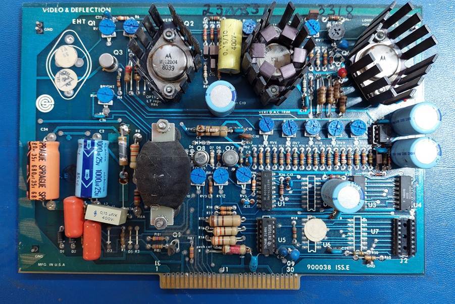
On closer examination the board has had a lot of mods. There are multiple track cuts, added components and changed components eg a resistor in a diode location.
There are no schematics, but there is a service manual. It has some block diagrams with some references to part IDs and some useful circuit description. It clearly indicates, though, that the high voltage circuitry changed a lot after serial number 10000.
Video control is unusual. Most CRTs use two deflection coils. The scan slowly downwards and quickly horizontally. Characters are formed progressively as a character line.
This system uses three deflection coils. The vertical deflection is performed in 25 steps under the control of a digital to analogue converter. Fly back is very fast: it can happen in the same time as the horizontal flyback.
Within each of the 25 lines each character is formed individually (I wonder if the lexitron does the same thing) using a series of vertical strokes.
This means that there are three deflection channels:
- Vertical: 50Hz in 25 steps with each step lasting 800us.
- Horizontal: Each sweep corresponds to one vertical step ie 800us.
- Write: Quick – 1.06Mhz
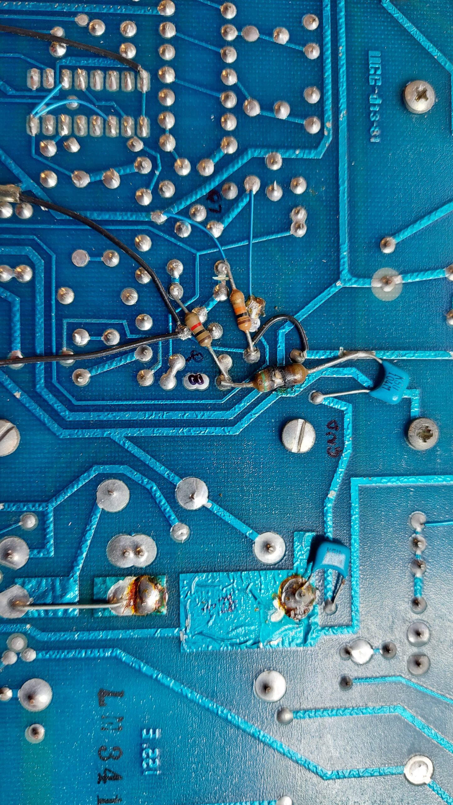
The hot resistor was tacked on to the back of the board among a bunch of mods. It seemed to be associated with the write deflection circuit. It was not going to make any sense without a schematic. I suppose I could have just started swapping components and I would have gotten there in the end (as it turned out). That’s not a technique that teaches much, though, so I sketched out the circuit instead.
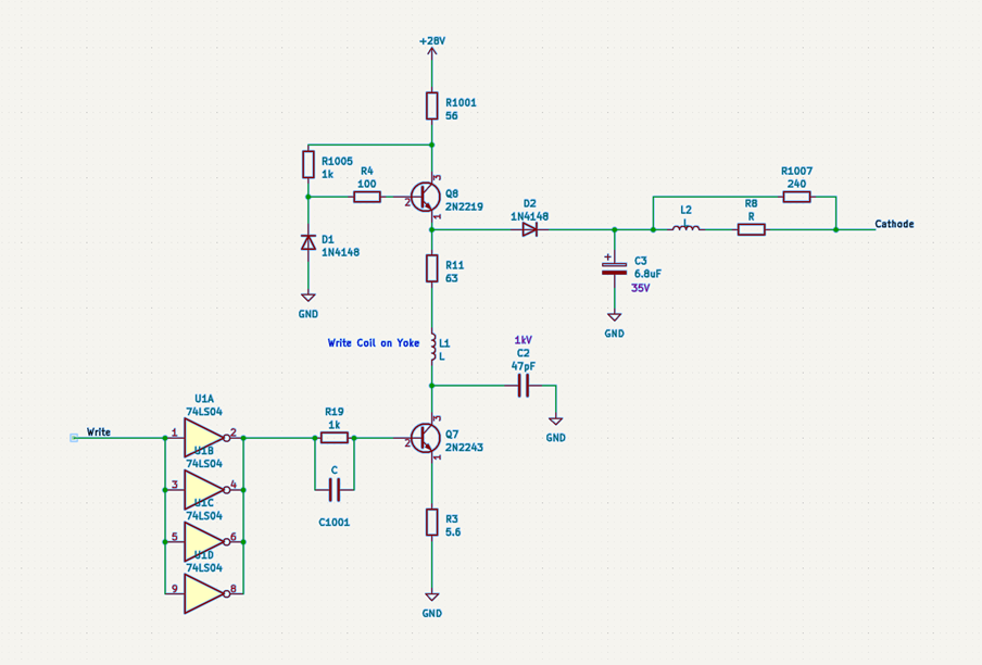
The hot resistor measured 56 ohms and was connected to the 26V supply and to the collector of Q8 which is involved in the generation of the write deflection signal. This circuit had been heavily modified. Part of that mod was to provide a power to the high voltage power supply. It also provides the cathode voltage (not shown on the block diagram in the manual). I found that this resistor continued to heat up even without the writing coil, the tube, or the high voltage power supply connected. That didn’t leave many places for the current to be going – just the unloaded cathode voltage circuit.
Looking at the Cathode supply, the tantalum appeared in good condition and the meter didn’t show a short. Putting it on a power supply did reveal a fault with a little more voltage. The tant was replaced with a couple of electrolytics and the burnt resister was replaced with a couple of smaller resistors in parallel.
As a side-effect of this exercise, I learnt about transistors (Q8 in this case) operating in an inverted mode. Nifty.
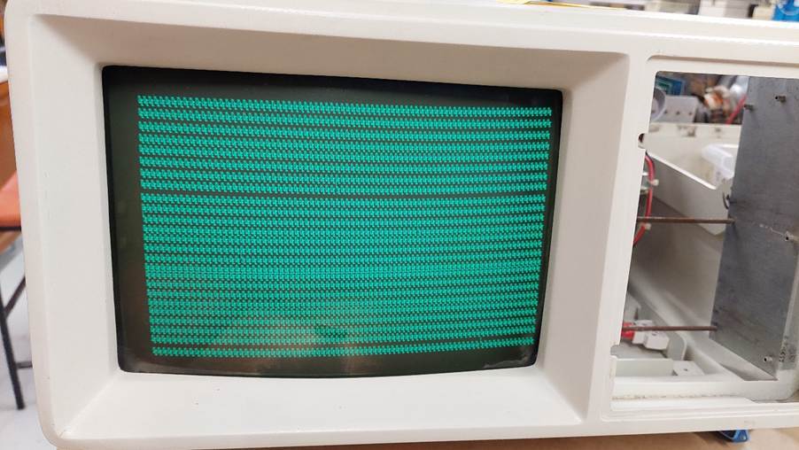
With this resolved, the screen came to life but with a limited horizontal deflection and no vertical deflection. I found that touching pots gave a significant effect and after some cleaning a full picture appeared – filled with rubbish – but that’s a different story.
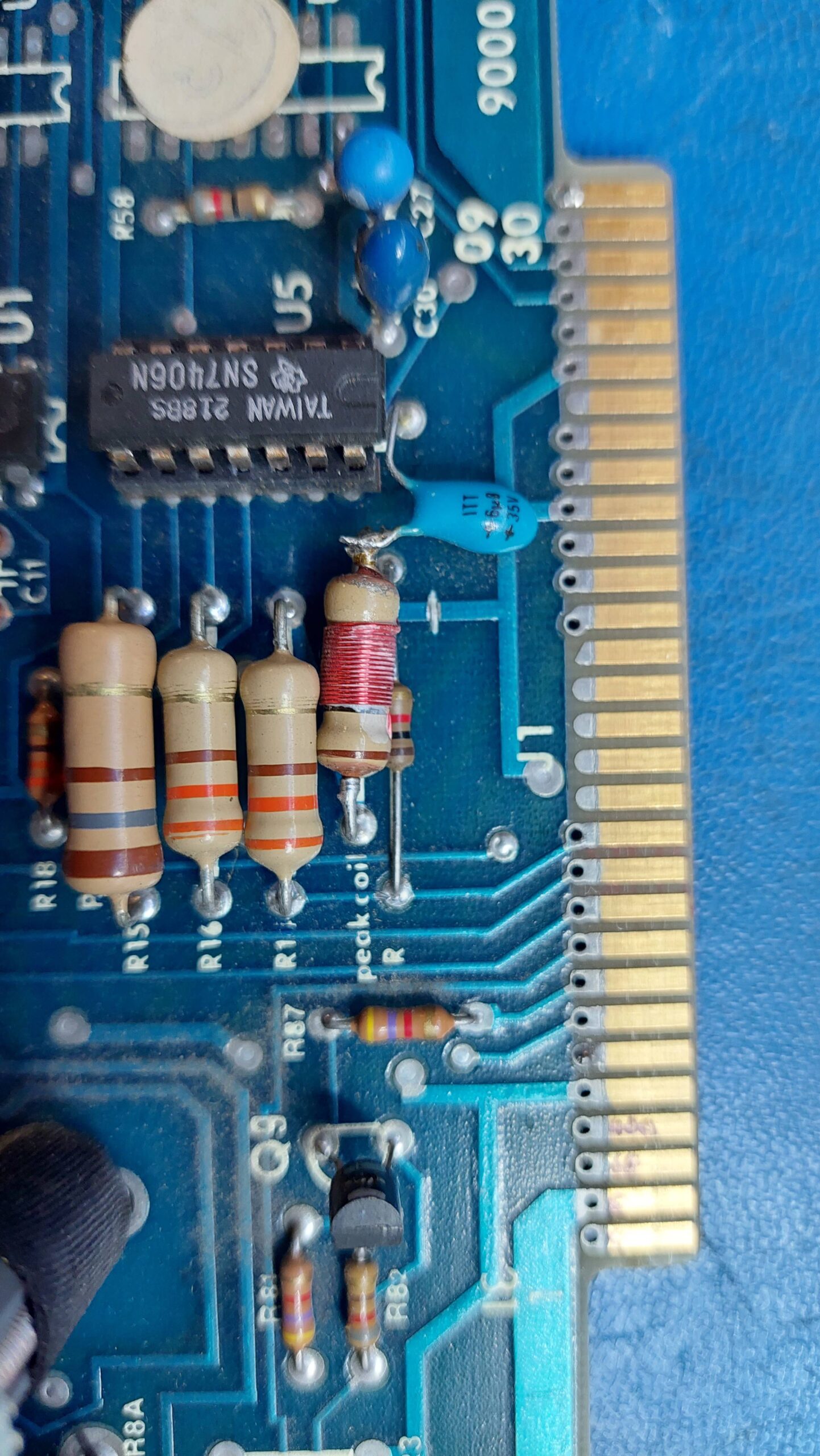
The vertical step D/A uses a resistive ladder. It has five adjustment pots. It looks like the 3rd bit is not quite right. Actually, they all look like they need some adjustment.
I did discover that some of the heatsinks are live so some electrical screw drivers are a good idea.