An enthusiast build – and i couldn’t even be sure that it’s complete.
Andrew, a friend from the ARC Group, has supplied me with a lot of funky gear including a box of S-100 cards, a couple of chassis, several 8″ floppy disk drives, and about 500 8″ floppy disks.
One of the challenges is that the relationships between all this kit was not obvious. This one i was only able to sort out because i found the source for some boot ROMs on one of the floppy disks. Even now i’m not sure if i have the original RAM card but the one i’m using does just fine.
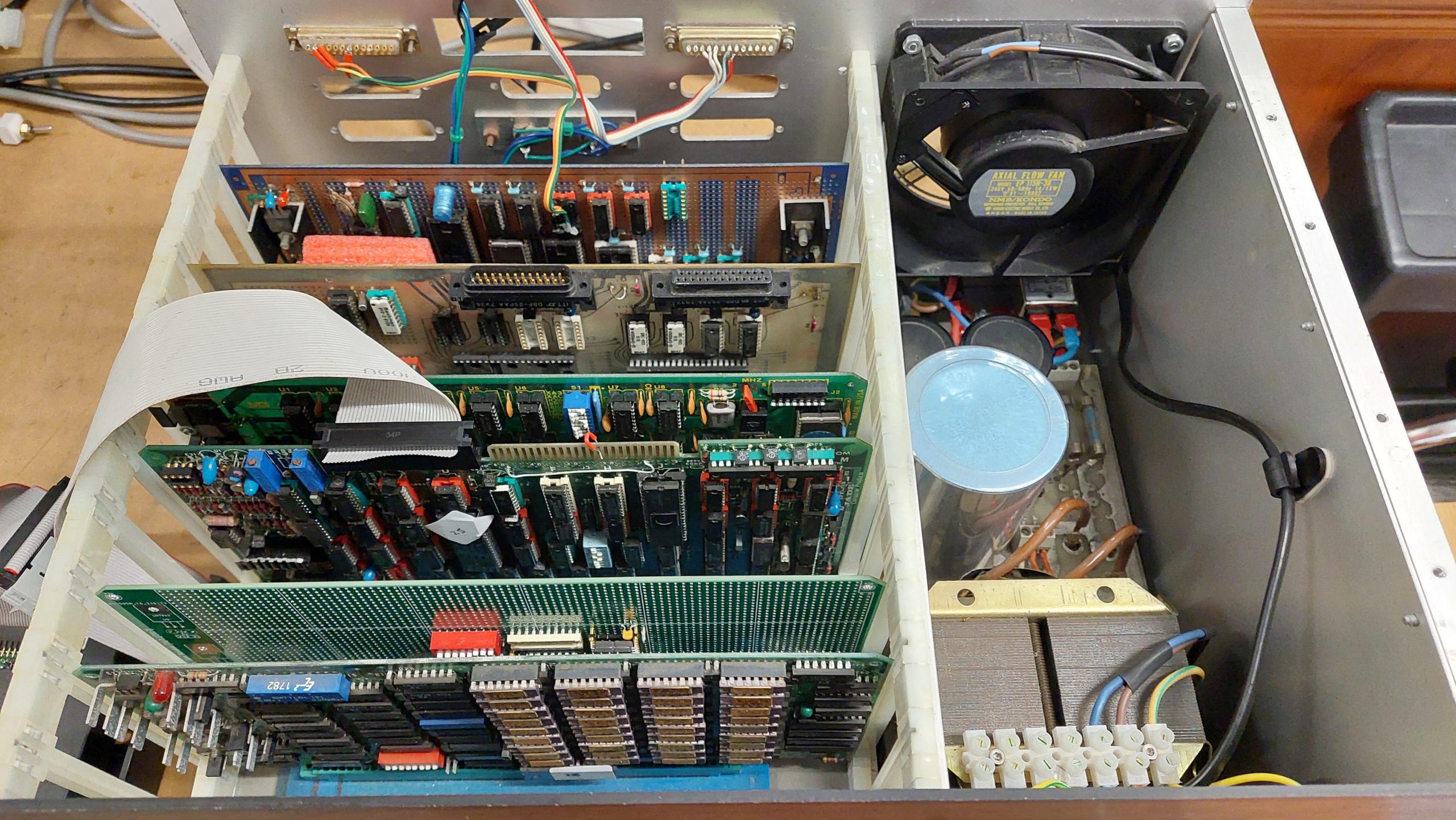
It uses the following cards:
Compupro 8085/86 CPU Card
Jade DD Floppy Disk Controller
A handcrafted wire-wrapped Serial & Parallel I/O and Speech Synthesiser card
A parallel card with real-time clock
Intersystems 256KDR
A recently constructed EPROM Card
I have not connected an 8″ drive to it as yet, but it boots JADE CP/M 2.2 from a gotek. The disk images are from the original floppy disks.
This machine is a reconstruction of a hobbyist built machine from the early eighties. It came to me in pieces in amongst a lot of other gear, so it wasn’t obvious to me that there was a complete computer there at all.
I had already rediscovered a Cromemco based computer which used half a dozen of the 29 S-100 cards that i’d received. I also had a rack, some 8″ drives, and a lot of 8″ disks which i had previously imaged.
Many of the disks were labelled as being Jade, and there was indeed a JADE DD Floppy Disk Controller amongst the cards. There were many more disks that used the JADE format.
There was also a Versafloppy II Floppy Disk Controller card, for which there were also a number of disks.
These were all CP/M disks so i was looking for a 8080, 8085 or Z80 processor board. The candidates were a Cromemco SBC which wasn’t a great fit with CP/M or a CompuPro 8085/88 CPU card which would work.
I also expected there to be some I/O and a card for a boot ROM. And RAM of course. There weren’t a lot of clues from the cards themselves.
Fortunately there was a disk labelled “Jade System BIOS Development which contained some assembler files for the CP/M bios and the boot ROM. At this point, i ruled the Versafloppy II out.
The boot ROM code had some comments identifying key components (8251, 8255 and 8253) on a W/W card. Once i found the card with that combination of components, i realised that W/W stood for wire-wrap. It was a hand-crafted board. It also has a speech synthesiser chip!
Looking at the chassis, i could see that the wires dangling from the back panel married up with empty sockets on the board.
A little while later i realised that there a couple more ports which may belong to this unidentified card:
It has a real-time clock on it.
I had several memory cards that could potentially be used, but given that the CPU card is capable of addressing more than 64k, i started with an Intersystems 256KDR.
This card is probably overkill, and i may swap it out in the future.
I do have an EPROM card, but it is made for 2708 EPROMs which i can’t program at present – i would need a new programmer.
Instead, i built a new card using a modern S-100 prototype card.
I needed an EPROM board to complete this computer and i could not see any easy way to obtain an eighties era card, so i had to knock one together myself.
I started with an S-100 Prototype board designed by John Monahan. This has all the buffers etc that end up on nearly every S-100 card, so a lot of the hard work is done.
John’s board designs are available for anyone to produce (as far as i can tell) and they are easy to get in the States. Not so easy in Australia, but on this occasion a batch turned up in Australia so a bought a few.
I had what i thought was the boot ROM code on an 8″ floppy disk. I’d previously extracted the files so i could have a good look.
The boot code indicated that the boot ROM would be located at F800 and occupy 2k. The Jade DD floppy disk controller uses a 1k window at F000. CP/M is set up for 60k, so there is also 1k free at F000. The boot allocates this to a Micropolis boot ROM similar to the one in the Sorcerer/Micropolis System.
I allowed for an 8kB EPROM (2764). J1-3 sets which address lines are used for decoding. To get just the top 2k, J1=J2.
Switch 1 sets the address of the ROM: in this case 00F800: 0000 0000 0000 1111 1000 0000 0000.
The highest address line decoded is A18, so the ROM will reappear at 04F800 but I don’t expect to ever have that much memory. That allows room for 256k of RAM.
My design worked immediately … no, of course it didn’t! I made several mistakes and i had trouble driving the phantom line (which disable RAM at the EPROM address). I eventually settled on the following:
I programmed an EPROM with the boot code that i found on the floppy disk.
There’s plenty of space left on the prototype card for some I/O if i ever run out of things to do.
The Jade Double D is notable for being an intelligent floppy disk controller. The onboard Western Digital FD1791 FDC chip is controlled by a Z80 processor. The CPU communicates with the DD through a 1kB window.
Although the card includes a processor and 2k of RAM it has no ROM. Instead, code must be injected by the CPU card. The code is embedded in the CPU boot ROM.
The boot code assumes that the window address must be set to F400. The jumpers were already correctly set.
This card supports 5.25″ drives on a 34 pin interface or 8″ drives on the 50 pin interface. Eventually i will use 8″ drives with this machine, but in the short term i just wanted to use a couple of goteks (with Flashfloppy).
The images that i wanted to use are from 8″ disks. These work fine in the gotek but because the gotek uses the 34 pin interface there were a couple of residual issues. There are a some signals expected by the boot ROM and the CP/M BIOS for the 8″ drives that are not on the 34 pin interface.
The first is the RDY signal which is supported by Flashfloppy on pin 34. This requires a link on the DD from pin 34 of the 34 pin interface to pin 22 of the 50 pin interface.
The second is that an 8″ drive can detect whether a disk is single or double-sided – the index hole is in a different location. For this, i added a switch to assert or negate the SIDES signal depending on which image i had loaded. I later copied all of the single sided disk images to double-sided disk images to make things a little simpler.
This card had a couple of hardware issues. The first was two shorted tantalums. The second was that, for whatever reason, two sockets had been butchered, and the chips soldered to the socket pins.
The cards were popped into the rack, including a partially tested EPROM card with a boot ROM programmed using a file from one of the 8″ floppy disks.
The source showed that on start-up the first serial port to receive a space character would become the console and offer to boot from the Jade DD.
The boot ROM source indicated a serial port speed of 9600. I used an IBM terminal setup accordingly.
I started with a CPU, EPROM, and I/O cards and proceeded to discover the various mistakes i had made with the EPROM card!
Once i could see that code was being read from the EPROM i added the RAM board and the Jade Double FDC. I could see data coming out of the UART, but it wasn’t making it to the terminal and that was because a shorted tantalum on the Jade board had blown the -12V fuse.
Once repaired, i got the boot screen.
I hooked up a couple of goteks and on the second image it booted.
High density 5.25″ disks have much the same capacity as 8″ double density disks, and they operate at the same data rate. A 5.25″ FDD typically has a few more tracks than an 8″ FDD.
This means that a floppy disk controller expecting to see an 8″ disk drive can potentially be fooled into working with an HD 5.25″ drive. This can be very handy if you don’t have an 8″ drive or if you want a more compact setup. This trick seems to work ok with a real HD drive or with a gotek/flashfloppy. 8″ disk images can be written to HD 5.25″ media without alteration using Greaseweazle, for example.
There are a few small issues. The first is the 8″ drive interface is usually 50 pins and the 5.25″ interface is usually 34 pins. The disk controller may have both interfaces (eg the Jade DD and the 16FDC) but not always (eg the Pulsar Little Big Board only has a 50 pin interface). If there is no 34 pin interface, then an adapter will be required. The 50 pin interfaces vary a bit, so a specific adapter may be required.
The second is that 8″ drives can detect whether a drive is single or double-sided and tell the host. The operating system driver may exploit this information (eg Jade DD CP/M) so there may need to be a way to fake this. For systems that use only single sided or only double-sided disks the signal can be tied appropriately otherwise a switch may be required – and if there are different drives in the system then it may be necessary to take the signal low through a diode from the drive select line.
Third is that 8″ drives typically produced a ready (RDY) signal. Without this signal, a host may just hang. This signal is available on many drives and can usually be setup on a gotek/flashfloppy but it may not be connected on the 34 pin interface. This can be overcome by connecting pin 34 on the 34 pin interface to the appropriate pin on the 50 pin interface.