I have worked on many CP/M and other computers which use 5.25″ 40 track floppy drives. It is often convenient during set-to-work and set-up to be able to access data from reliable sources, including known good floppy disk drives and solid state drives.
It is also useful to be able to augment any existing drives with additional drives. Often i would need to swap a physical drives with a solid state drive.
I often ended up with floppy disk drives and power supply spread out over a bench, and every time i used them i would need to configure them.
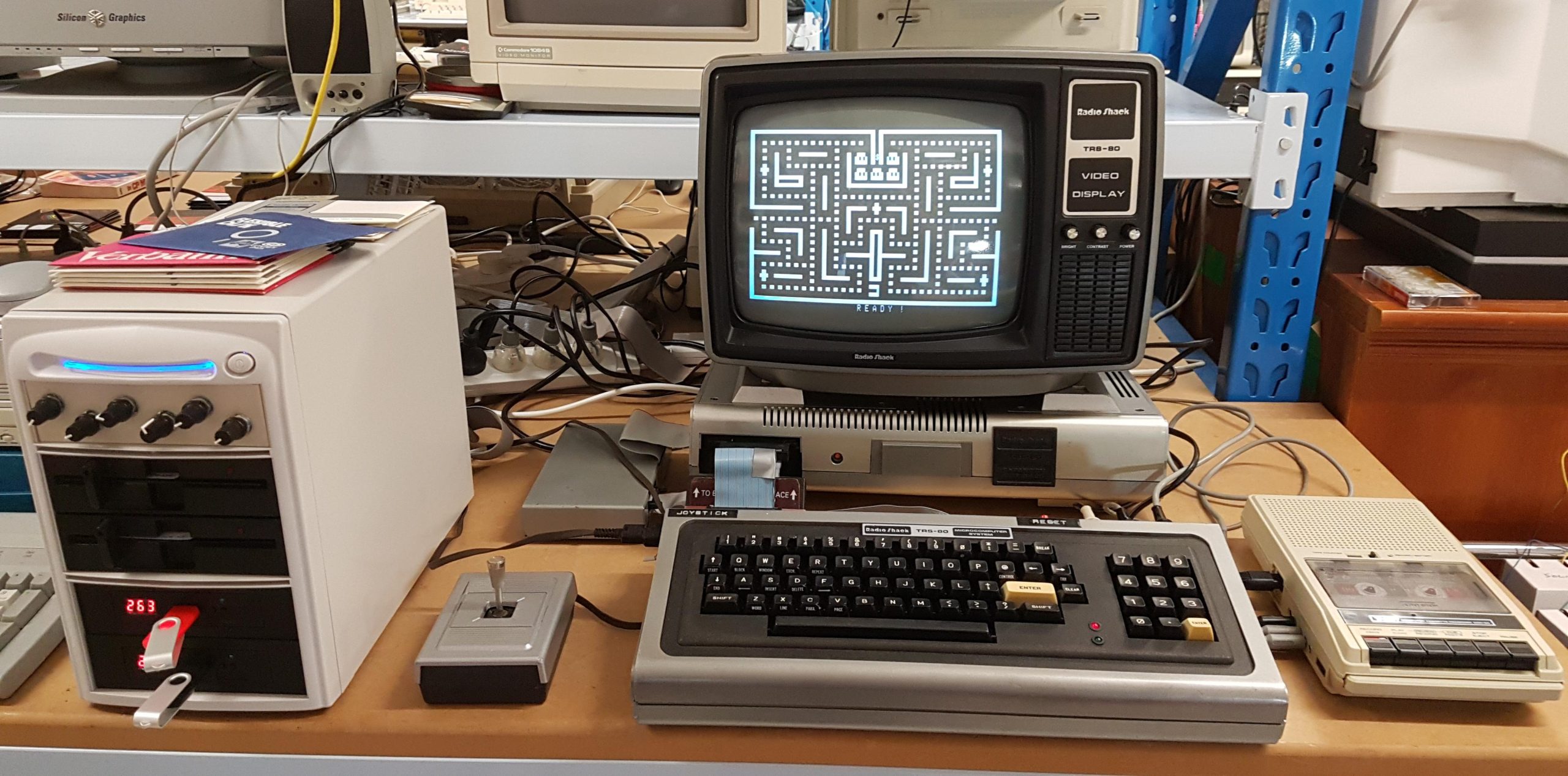
I thought a better solution may be to build up a neat unit with some switches that would allow me to easily reconfigure some drives. I found a relatively cheap CD-ROM duplicator case that had a power supply and enough space for four 5.25″ drives and a small switch panel.
I was doing this again, i would probably use an arduino to perform the various configuration options, but i made it work with some cheap rotary switches. The solution is very much driven by these switches.
The Goteks, modified with FlashFloppy, are also able to emulate 77 track 8″ drives, 80 track 5.25″ drives, and 3.5″ inch drives. In principle, the physical drives could be swapped out for other drive types, but 8″ drives might exceed the available space!
Normally, 5.25″ drives can be configured with 3 or 4 individual drive select lines. With the coming of PCs and the floppy disk drive cable twist, only one was ever used. Subsequent 3.5″ disk drives only provided 1 or 2. The gotek is modelled on a 3.5″ drive, and it has two: DS0 and DS1. Then the two physical drives are DS2 and DS3.
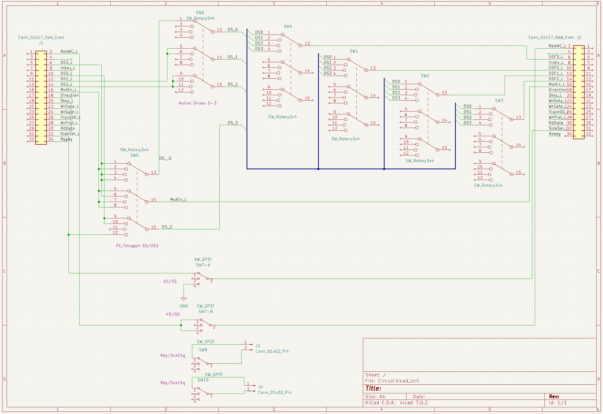
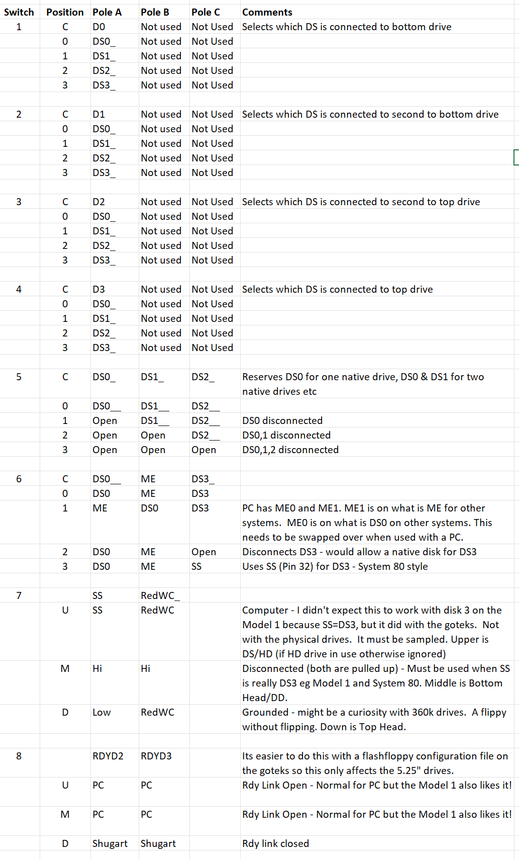
The switches had 3 ganged 4 position switches (poles). The first 4 switches are simply used to connect a computer drive select line to a floppy disk drive select line (it doesn’t matter which, as long as the drive is configured to use it). DS1 is the PC convention.
The next switch complicates matters. It, too, is a drive select intermediary. It is used to accommodate existing drives from 0 to 3. If you have four existing drives, then this unit cannot be used. If the user wants to use 1 existing drive and, therefore, no more than three drives in the unit, then the fifth switch is set to 1. With this setting, DS0 is reserved for the existing drive. The unused drive in the unit should be parked at DS0, but it will never be selected.
My brain was already starting to hurt, but it got much worse with the sixth switch. The floppy disk drive interface has evolved. This covers some of the variations:
https://retrocmp.de/fdd/general/floppy-bus.htm#pin34
Firstly, IBM PC introduced a variation that allowed the A and B drives to be configured identically. This involved twisting part of the cable to swap over the Motor Enable and the Drive Selects. It also uses the Ready signal as a Disk Change signal.
There are other variations regarding Side Select, Drive Select 3 (4th select). I’ve covered some of them as i’ve encuntered them.
Switch 6 position 0 is for most drives. Position 1 is for PCs. Only two drives can be used with a PC. Position 3 replaces Side Select on pin 32 with DS3. This is used on the System 80 which has only single-sided drives.
There are more variations. Switches 7 and 8, on the back of the unit, are double-pole double-throw switches. Switch 7 deals with sides and densities. The Upper position is for double-sided operation and the middle position is for single-sided operation. The bottom position would allow the top head to be used instead of the bottom head; a flippy without flipping.
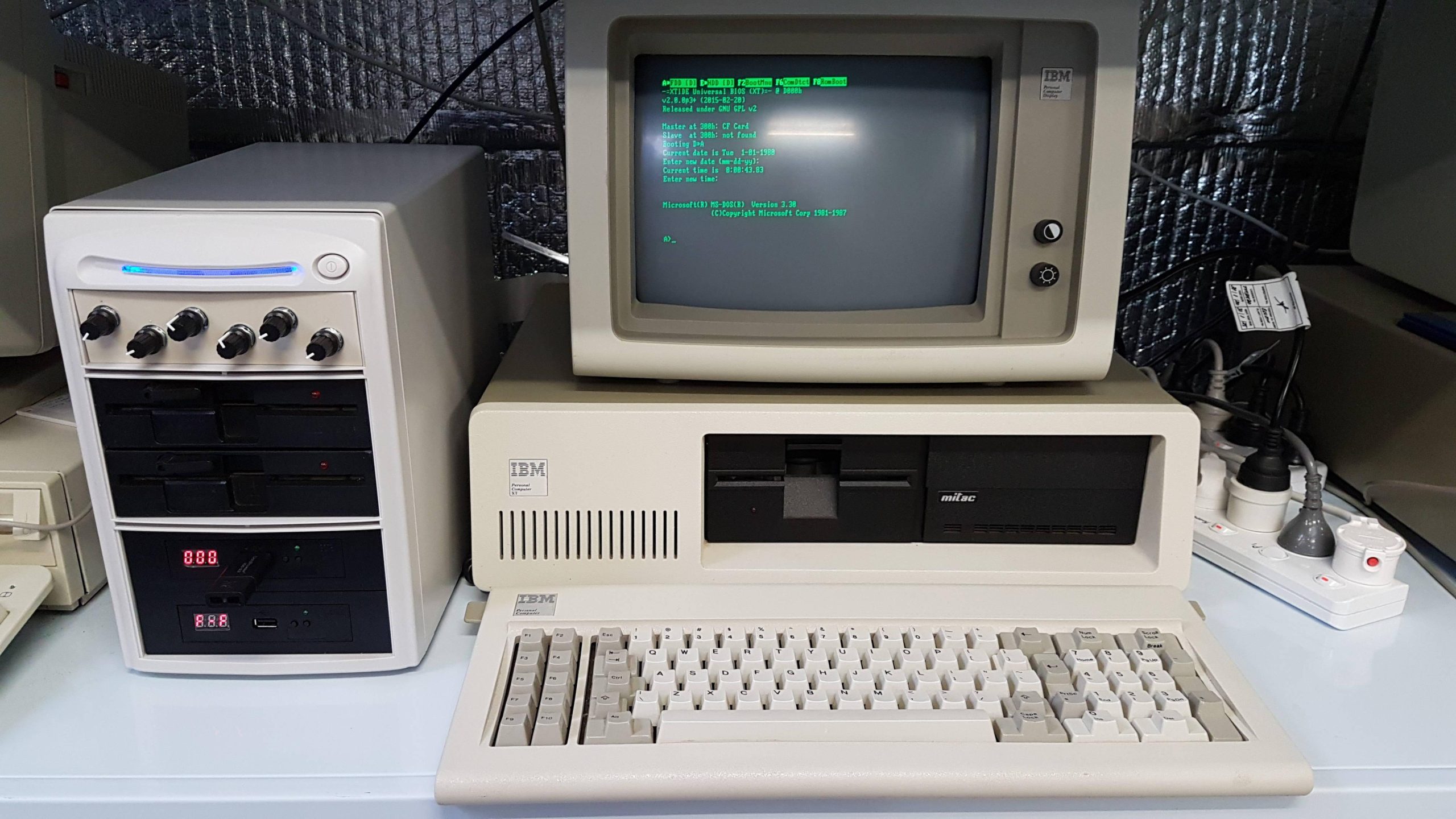
Switch 8 changes the floppy drive configuration for pin 34: Ready or Disk Change. Up/Middle for a PC but down for other hosts. The TRS-80 Model I liked the PC position; i do not know why.
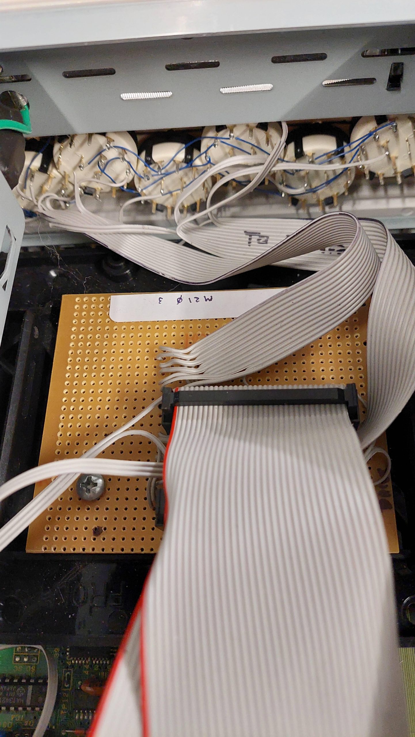
Implementation is a little ugly, but it seems to be effective.
I’ve tried this out with a lot of systems including some that i didn’t anticipate when i built it.
A summary of the switches: