The Sony power supply gave me some grief not long after i got the machine. When i pulled the board out, it appeared to be recapped by a previous owner, but the PCB was still covered with a lot of residue from the previous capacitors. I gave it a good clean, dried it out, tested it, and with the machine booting, i claimed victory.
But then, sometime later, the machine refused to start up. There was nothing on the screen. The supply voltages were fine, but I wasn’t sure about the Power On Reset (POR) (grey wire) which seemed to always be low.
I took the unit out and put a disk on it for minimum load. The POR line stayed low, but I found a maintenance manual which said that it was open-collector and once I added a pullup resistor it worked fine.
I gave the supply a clean again – the solder resist is coming off where the capacitors leaked, so I scraped it away and tinned the tracks for protection. I put it back in and the POR signal started to do its thing, but still there was no boot.
The service manual suggested putting a monitor on serial port A and this showed diagnostics running continuously.
Depending on how much was plugged in (eg hard disk drive, floppy) the diagnostics would restart. Once the drive spun up, this would sometimes come good. A closer look at the POR showed that it was “going off” sporadically – seemingly worse with load. The supply lines seemed fine.
I took the supply out again and loaded it up with some more disks. Sure enough, the POR line misbehaved.
I couldn’t find schematics, so I was flying somewhat blind. I worked back from the POR line, which eventually led to what I think is an LM358 dual op amp (very hard to read), the output of which was indirectly driving the POR line. The amp is configured as an integrator. Despite this, it was clearly not riding out some bumps in whatever it was sensing – which seems to be the 5V line – although not directly because the 5V was clean.
The power supply is switched mode. What was coming across the transformer was very complicated, and I couldn’t make sense of it. It looked like the signal coming across the isolation transformer was the issue, with some significant lumps and bumps at 100Hz, so I moved back to the high voltage side – which I hate.
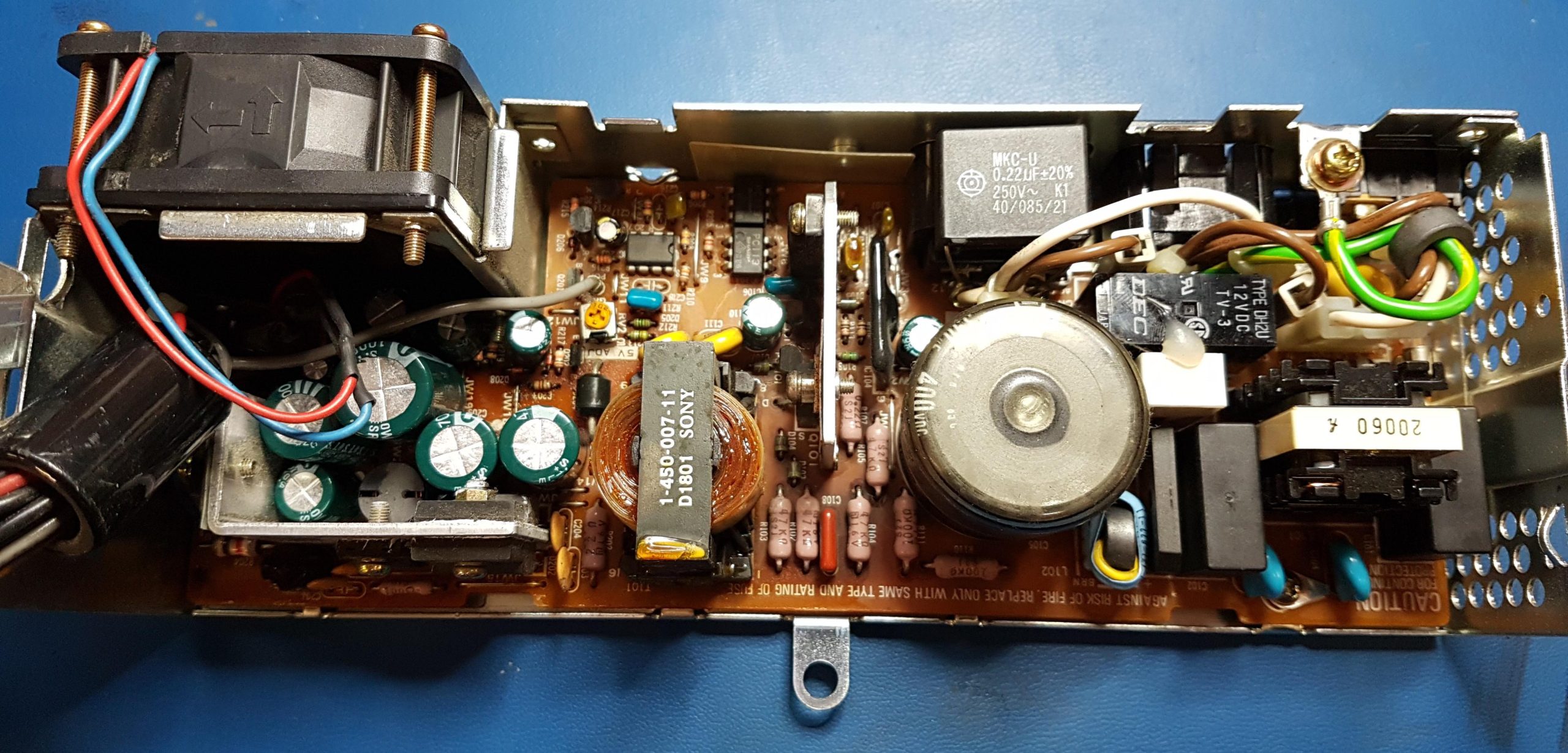
It has a bridge rectifier with a large filter cap, which looked like it was the only original electrolytic original unit. The bridge rectifier seemed fine. There is a series surge limiting resistor that’s shorted by a relay controlled from the low voltage side by an optical isolator. Another optical isolator provides the feedback path for regulation.
The DC voltage on the filter cap was about 240V. Usually I’d expect something a bit higher than that – around the 320V to 340V mark – the peak of the 240V waveform. There also seemed to be a very large AC component. I didn’t want to put the scope on, but I thought the cap might not be at its best.
I pulled it out – it measured a few nF. It wouldn’t hold charge from a battery.
The supply still works as long as the load is light – no hard disk drive; a remarkable effort from the switcher given the fault. It seemed to be quite effective at tracking the rectified AC although this probably made life difficult for the switching transistor.
Once the replacement cap was fitted, the DC level and 100Hz ripple on the rectifier were much healthier, the POR good, and the system was happy.